SLB150, SLB300, SLB1200, SLB600, SLB200 specifications
The Ingersoll-Rand SLB series of portable and stationary air compressors comprises several models, including the SLB200, SLB600, SLB1200, SLB150, and SLB300. These compressors are renowned for their reliability, performance, and innovative technologies, making them ideal for a wide range of industrial applications.The SLB200 model comes equipped with a robust design that emphasizes mobility and efficiency. It features a compact footprint while delivering up to 200 CFM, making it suitable for smaller job sites or where space is limited. The SLB200 integrates advanced control systems that optimize airflow and pressure management, ensuring consistent performance under varying load conditions.
Next in the lineup is the SLB600, a powerhouse that delivers significantly higher capacity, reaching up to 600 CFM. This model offers advanced noise reduction technologies, which help minimize operational noise, making it an excellent choice for urban work sites. With its high-efficiency airend technology, the SLB600 also significantly improves fuel consumption, enabling cost-effective operation over the long term.
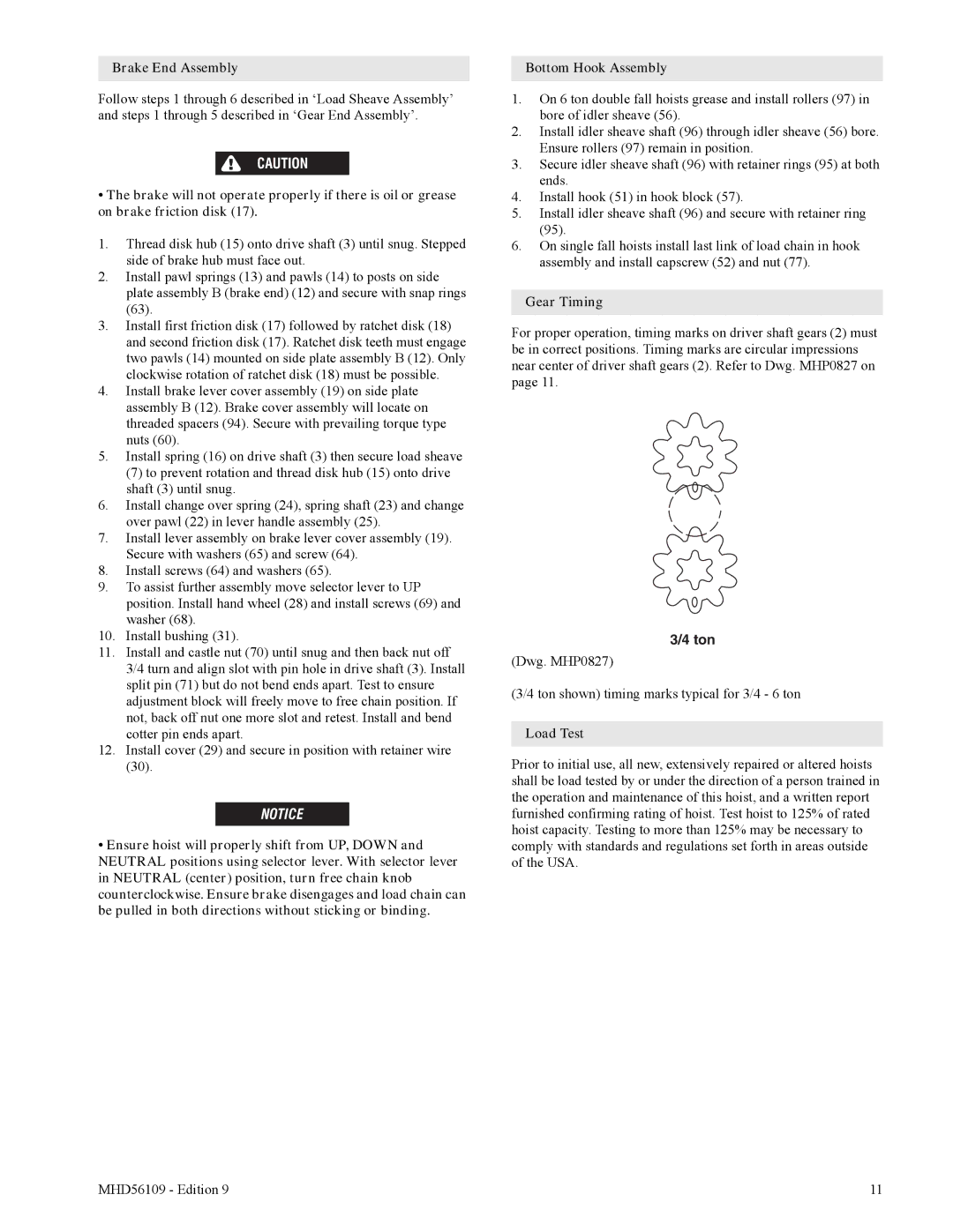
For those requiring even more power and versatility, the SLB1200 stands out, providing up to 1200 CFM. This model is engineered for heavy-duty applications, featuring durable construction that withstands rugged use. The SLB1200 comes equipped with advanced diagnostics and monitoring systems, allowing operators to track performance metrics in real-time. This feature enhances maintainability and helps prevent unexpected downtime.
The SLB150, while smaller, does not compromise on performance. Delivering 150 CFM, it is particularly valued in industries where portability is crucial. The SLB150 operates efficiently in both stationary and mobile applications, making it a favorite among contractors and repair professionals. Its lightweight design and integrated wheels ensure easy transport without sacrificing power.
Finally, the SLB300 model fills the gap for those needing a mid-range option with superior efficiency. Operating at up to 300 CFM, it strikes a balance between power and practicality. This model is equipped with enhanced filtration systems to ensure the highest air quality, which is essential for applications sensitive to contamination.
Overall, the Ingersoll-Rand SLB series is characterized by its commitment to innovation, reliability, and efficiency, catering to the diverse needs of modern industries while ensuring optimal performance and durability across all models.