LA-2A specifications
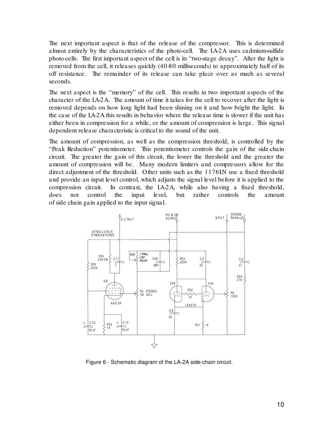
The Inova LA-2A is a sophisticated optical compressor renowned for its classic design and exceptional sound quality. Hailing from the lineage of legendary optical compressors, the LA-2A combines vintage warmth with modern reliability, making it a staple in professional recording studios globally.One of the main features of the LA-2A is its opto-electronic gain reduction circuit, which utilizes a light-dependent resistor (LDR) and a sealed optical element to achieve compression. This unique mechanism provides a smooth and transparent compression, allowing the audio signal to maintain its natural dynamics while controlling peaks effectively. The optical design contributes to a musical response, widely regarded as one of its defining characteristics.
The LA-2A also features a simple and intuitive interface. It includes essential controls such as Peak Reduction, which adjusts the level of gain reduction, and Make-Up Gain, which compensates for any lost level after compression. The device typically has two modes: the Compress mode for moderate compression and the Limit mode for more aggressive limiting. This flexibility makes it suitable for a variety of audio sources, from vocals to instruments.
Another noteworthy characteristic is its true tube circuitry. The LA-2A employs a vacuum tube in its audio path, contributing to its warm tonal character. This tube coloration enhances the richness of audio signals, making the device particularly popular for vocals and bass, where presence and depth are paramount.
Additionally, the build quality of the LA-2A is exceptional. The chassis is constructed from durable materials, ensuring longevity and reliability in demanding studio environments. Its vintage aesthetic features analog VU meters, adding to its charm while providing visual feedback of the gain reduction.
Inova has modernized the LA-2A with contemporary features while preserving its classic sound. Enhanced technologies such as improved signal-to-noise ratio and updated component designs ensure that the LA-2A remains competitive in today's digital landscape.
Ultimately, the Inova LA-2A is a beautifully crafted compressor that delivers a unique sonic signature. It combines vintage appeal with modern functionality, making it an essential tool for audio engineers and music producers seeking to achieve professional-grade mixes. Its smooth compression characteristics, intuitive controls, and durable design are testaments to its lasting legacy in the world of audio processing.

