Connecting a DVD Player
An appropriate option board [H] [I] should be installed to connect a DVD player.
The description here guides you to make connection between the
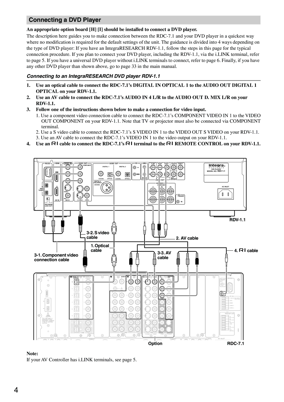
Connecting to an IntegraRESEARCH DVD player RDV-1.1
1.Use an optical cable to connect the
2.Use an AV cable to connect the
3.Follow one of the instructions shown below to make a connection for video input.
1.Use a component video connection cable to connect the
2.Use a S video cable to connect the
3.Use an AV cable to connect the
4.Use an ![]() cable to connect the
cable to connect the ![]() terminal to the
terminal to the ![]() REMOTE CONTROL on your
REMOTE CONTROL on your
RS 232 | HDMI | VIDEO IN | VIDEO OUT | AUDIO OUT | IR | D. MIX | FRONT | SURR 1 | CENTER | SURR 2 |
|
|
| COMPONENT |
|
|
|
|
|
|
|
Y | Y | DIGITAL 1 | DIGITAL 2 | L |
|
| L | |
|
| IN |
|
| ||||
|
|
|
|
|
|
|
| DVD PLAYER |
OUT |
|
|
|
|
|
|
| MODEL NO. |
PB | PB |
|
| OUT | R |
|
| R |
|
|
|
|
| REMOTE |
| SUB |
|
|
| COAXIAL OPTICAL | COAXIAL | OPTICAL | CONTROL | AUDIO OUT | WOOFER |
|
PR | PR | DIGITAL 2 |
|
|
|
|
| |
|
|
|
|
|
| |||
|
| ( BALANCED) |
|
|
| HD VIDEO OUT |
|
|
|
| AES/EBU |
|
|
|
|
| |
IN |
|
|
|
| COMPONENT |
| AC INLET | |
|
|
|
| Y | PB | PR | ||
S400 |
|
|
|
|
|
|
|
|
( AUDIO) |
|
|
|
| 1 |
|
|
|
S VIDEO |
|
|
|
|
|
|
| |
|
|
| 12V |
|
|
| TRIGGER |
| VIDEO |
| 2 |
| S VIDEO | VIDEO | |
1 | 1+ 2 |
| IN |
SURR MODE |
|
| |
(AUDIO OUT) |
|
| |
|
|
| |
|
|
|
|
cable |
| 2. AV cable |
|
1.Optical |
|
|
|
cable | 4. | cable | |
|
|
| |
cable |
|
| |
connection cable |
|
| |
|
|
|
A![]() B
B
“Net
is a trademark of Onkyo Corporation.
ETHERNET
C | DIGITAL IN | D | DIGITAL IN | E |
| - CH | F | AUDIO IN | G |
|
|
|
|
|
|
| MULTI | R | L | R | L |
| OPTICAL |
| COAXIAL | FR | FL | IN 1 | ||||
| 1 | 1 |
|
|
|
| PH |
| 4 |
|
|
|
|
| SUB |
| C |
|
|
|
|
| 2 | 2 |
|
|
|
|
|
| 5 |
|
|
|
|
|
|
|
|
| GND |
|
|
|
|
|
| SR |
| SL | R | L |
|
|
| 3 | 3 |
|
|
|
| 1 |
| 6 |
|
| SBR | SBL |
|
|
|
4 | 4 | 2 |
| 7 |
|
| FR | FL |
|
|
|
5 | 5 | 3 |
| 8 |
|
| SUB | C |
|
|
|
6 | 6 | 1 |
| 9 |
|
| SR | SL |
|
|
|
1 | 1 | 2 |
| 4 |
|
| SBR | SBL |
|
|
|
2 | 2 | 3 |
| 5 |
|
| OUT | R | L | OUT R | L |
MULTI - CH IN 2
H S VIDEO | VIDEO |
IN | IN |
1
2
3
4
5
6
1
2
OUT
S VIDEO | VIDEO |
I | COMPONENT | J |
| K | L |
VIDEO |
| ||||
IN 1 | IN 2 | COMPONENT VIDEO |
| ANTENNA | |
|
| ((HDHD/BNC/BNC)) | IN |
|
|
| Y |
| Y |
|
|
|
|
|
|
| |
| PB |
|
|
|
|
|
|
| PB |
|
|
| PR |
|
| FM |
|
|
|
|
|
| |
OUT 1 | IN 3 |
|
| 75 |
|
|
|
|
| ||
| Y |
| PR |
|
|
|
|
|
|
| |
|
|
| OUT |
|
|
| PB |
| Y |
|
|
|
|
| AM |
| |
| PR |
|
|
|
|
|
|
| PB |
|
|
3 |
|
|
|
|
|
4 |
|
| PR |
|
|
|
|
|
|
| |
OUT |
|
|
|
|
|
VIDEO | S VIDEO |
|
|
|
|
HDMI |
| 12 V | RS232 |
| TRIGGER |
| |
|
| OUT |
|
| IN 1 | E |
|
|
|
| |
|
|
| IR IN |
+12V DC PWR SUPPLY
20mA MAX.
GND
IN 2
MAIN
ZONE 2
ZONE 3
12V TRIGGER OUT
A
200mA MAX.
B
100mA MAX.
C
100mA MAX.
GND
D
100mA MAX.
E
TOTAL | UDD |
100mA MAX. |
OUT
(ASSIGNABLE)
(ASSIGNABLE) | (SINGLE) | AC INLET |
Option |
Note:
If your AV Controller has i.LINK terminals, see page 5.
4