Manuals
/
Intel
/
Computer Equipment
/
Network Card
Intel
8 LAN
manual
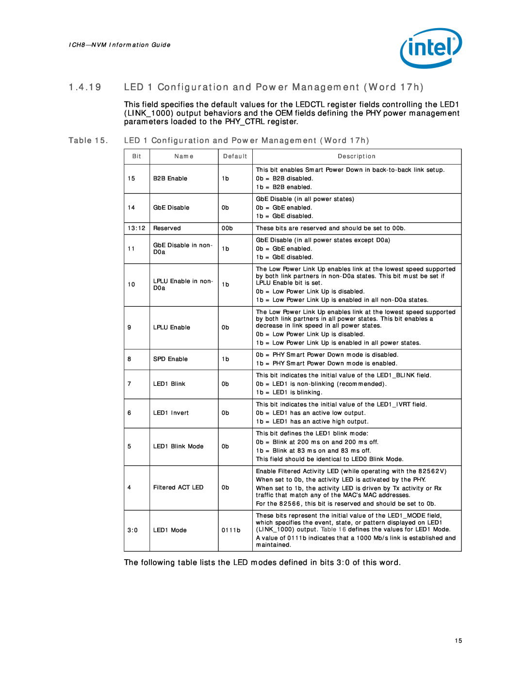
LED 1 Configuration and Power Management Word 17h
Models:
8 LAN
1
15
28
28
Download
28 pages
9.08 Kb
12
13
14
15
16
17
18
19
Page 15
Image 15
Page 14
Page 16
Page 15
Image 15
Page 14
Page 16
Contents
316234-006Revision
January
Intel Corporation P.O. Box 5937 Denver, CO
Tables
Contents
Revision History
1.2NVM Programming Procedure Overview
1.0Non-VolatileMemory NVM
1.1Introduction
Figure 1. LAN NVM Regions
BIOS Region ME Region GbE Region Flash Descriptor
Region
1.3EEUPDATE Utility
1.3.1Command Line Parameters
Example 1. EEUPDATE /D file1.eep
Table 1. LAN NVM Address Map
1.4LAN NVM Format and Contents
1.4.1Ethernet Individual Address Words 00h - 02h
1.4.2Reserved Word 03h
Reserved Word 03h
1.4.6Reserved Word 07h
1.4.3Reserved Word 04h
1.4.4Image Version Information Word 05h
1.4.5Reserved Word 06h
PCI Initialization Control Word Word 0Ah
1.4.8PCI Initialization Control Word 0Ah
1.4.9Subsystem ID Word 0Bh
1.4.10Subsystem Vendor ID Word 0Ch
1.4.12Vendor ID Word 0Eh
1.4.14LAN Power Consumption Word 10h
LAN Power Consumption Word 10h
1.4.11Device ID Word 0Dh
Shared Initialization Control Word 13h
1.4.15Shared Initialization Control Word 13h
Extended Configuration Word 1 Word 14h
1.4.16Extended Configuration Word 1 Word 14h
1.4.17Extended Configuration Word 2 Word 15h
1.4.18Extended Configuration Word 3 Word 16h
LED 1 Configuration and Power Management Word 17h
LED Modes
1.4.20LED 0 and 2 Configuration Defaults Word 18h
1.4.22
LED 0 and 2 Configuration Defaults Word 18h
1.4.21
Future Initialization Word 1 Words 19h
1.4.23.1Boot Agent Main Setup Options Word 30h
Table 18. Boot Agent Main Setup Options
1.4.23PXE Words Words 30h - 3Eh
prompt message appears, if enabled by DIM
NVM Information Guide-ICH8
Disable Protocol Select
1.4.24Checksum Word 3Fh
1.4.23.4IBA Capabilities Word 33h
Table 21. IBA Capabilities
LAN NVM Contents
Appendix A ICH8 NVM Contents and Sample Images
A.1 82566DM NVM Image with ICH8
A.2 82566MM NVM Image with ICH8M
A.3 82566MC NVM Image with ICH8
A.4 82562V NVM Image with ICH8
Note This page intentionally left blank
Top
Page
Image
Contents