English
7) DIMM_LED
Do not remove memory modules while DIMM LED is on. It might cause short or other unexpected damages due to the 2.5V stand by voltage. Remove m emory m odules only when AC Power cord is disconnected.
+ ![]()
![]() -
-
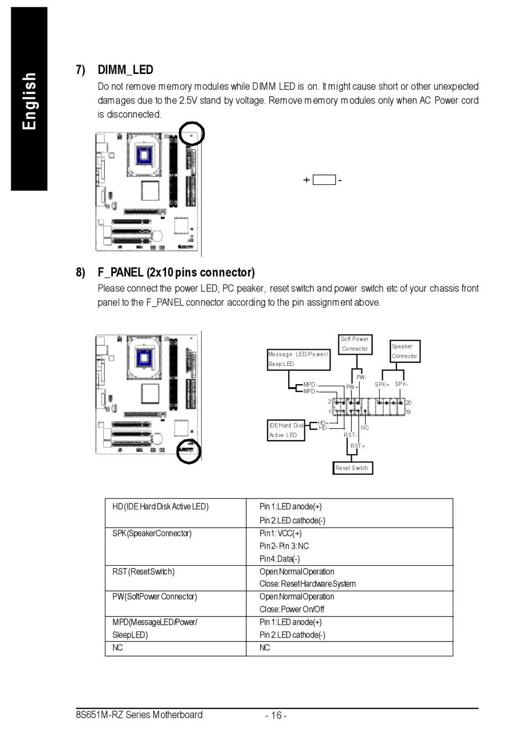
8) F_PANEL (2x10 pins connector)
Please connect the power LED, PC peaker, reset switch and power switch etc of your chassis front panel to the F_PANEL connector according to the pin assignment above.
|
|
|
| So ft Pow er |
|
|
| Spea ker | ||||||||
|
|
|
| Co nnector |
|
|
| |||||||||
Me ssa g e LED /Po w e r / |
|
|
| Conne ctor | ||||||||||||
|
|
|
|
|
|
|
|
|
| |||||||
Sle ep L ED |
|
|
|
|
|
|
|
|
|
|
|
|
|
|
|
|
MPD - |
|
|
|
|
|
|
| PW - | SPK+ | SP K- | ||||||
|
|
|
|
|
| PW + |
|
| ||||||||
MPD + |
|
|
|
|
|
|
|
|
|
|
|
|
|
|
| |
|
|
|
|
|
|
|
|
|
|
|
|
|
|
| ||
| 2 1 |
|
|
| 1 |
|
|
| 1 |
|
|
|
| 20 | ||
|
|
|
| |||||||||||||
| 1 1 |
|
|
|
| 1 |
|
|
|
| 19 | |||||
|
|
|
|
|
|
|
|
| ||||||||
ID E H ard Di sk | HD+ |
|
|
|
|
|
|
|
|
|
|
|
|
|
| |
| HD - |
|
|
|
|
|
| N C |
|
|
|
|
|
| ||
Acti ve L ED |
|
|
|
| R ST - |
|
|
|
|
|
|
|
| |||
|
|
|
|
|
|
|
| R ST + |
|
|
|
|
|
| ||
|
|
| Re set Switch |
|
|
|
|
|
| |||||||
HD (IDE Hard Disk Active LED) | Pin 1:LED anode(+) |
| Pin 2:LED |
|
|
SPK(SpeakerConnector) | Pin1: VCC(+) |
| Pin 2- Pin 3:NC |
| |
RST (ResetSwitch) | Open:NormalOperation |
| Close:ResetHardware System |
|
|
PW(SoftPower Connector) | Open:NormalOperation |
| Close:Power On/Off |
|
|
MPD(MessageLED/Power/ | Pin 1:LED anode(+) |
SleepLED) | Pin 2:LED |
NC | NC |
|
|
8S651M | - 16 - |