Installation Guide for POC Board
6.Install storage devices. There is one IDE and one SATA connector on the POC board, which supports up to 3 hard drives (two PATA IDE
Note: Master/slave settings are determined by a jumper on each IDE device. Consult the device label/documentation to verify that the jumper is set correctly for the configuration you choose. A
Warning: Failure to properly align the IDE cable may damage the POC board and/or the hard drive.
7.Install the
a)Verify that the jumper on the
b)Connect the unused end of the IDE cable you have already attached to the POC board to the
c)Connect the
8.Connect the monitor. Connect the monitor cable to the VGA port.
9.Connect the keyboard and mouse. Connect the KB/Mouse cable to the
Note: If you connect the USB keyboard and USB mouse to the front panel, you must connect the USB cable from the front panel to the connector CN5 on the board first.
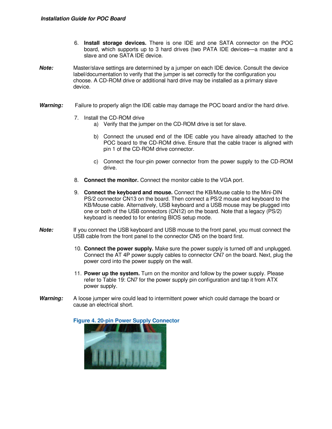
10.Connect the power supply. Make sure the power supply is turned off and unplugged. Connect the AT 4P power supply cables to connector CN7 on the board. Next, plug the power cord into the power supply on the wall.
11.Power up the system. Turn on the monitor and follow by the power supply. Please refer to Table 19: CN7 for the power supply pin configuration and tap it from ATX power supply.
Warning: A loose jumper wire could lead to intermittent power which could damage the board or cause an electrical short.