Connectors and Jumpers
3.2List of Connectors
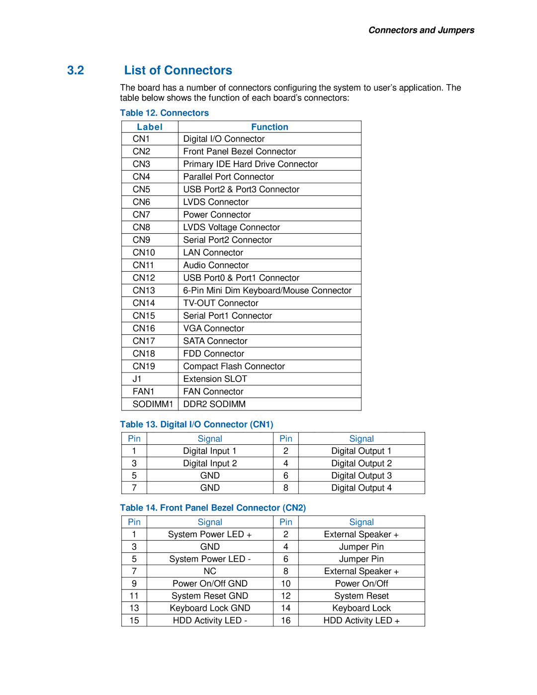
The board has a number of connectors configuring the system to user’s application. The table below shows the function of each board’s connectors:
Table 12. Connectors
| Label |
| Function |
|
| ||||
| CN1 |
| Digital I/O Connector |
|
|
|
| ||
|
|
|
|
|
|
|
|
| |
| CN2 |
| Front Panel Bezel Connector |
|
| ||||
|
|
|
|
|
|
|
|
| |
| CN3 |
| Primary IDE Hard Drive Connector |
|
| ||||
|
|
|
|
|
|
|
|
|
|
| CN4 |
| Parallel Port Connector |
|
|
|
| ||
|
|
|
|
|
|
|
|
| |
| CN5 |
| USB Port2 & Port3 Connector |
|
| ||||
|
|
|
|
|
|
|
|
|
|
| CN6 |
| LVDS Connector |
|
|
|
| ||
|
|
|
|
|
|
|
|
|
|
| CN7 |
| Power Connector |
|
|
|
| ||
|
|
|
|
|
|
|
|
| |
| CN8 |
| LVDS Voltage Connector |
|
| ||||
|
|
|
|
|
|
|
|
|
|
| CN9 |
| Serial Port2 Connector |
|
|
|
| ||
|
|
|
|
|
|
|
|
|
|
| CN10 |
| LAN Connector |
|
|
|
| ||
|
|
|
|
|
|
|
|
|
|
| CN11 |
| Audio Connector |
|
|
|
| ||
|
|
|
|
|
|
|
|
| |
| CN12 |
| USB Port0 & Port1 Connector |
|
| ||||
|
|
|
|
|
|
|
| ||
| CN13 |
|
| ||||||
|
|
|
|
|
|
|
|
|
|
| CN14 |
|
|
|
|
| |||
|
|
|
|
|
|
|
|
|
|
| CN15 |
| Serial Port1 Connector |
|
|
|
| ||
|
|
|
|
|
|
|
|
|
|
| CN16 |
| VGA Connector |
|
|
|
| ||
|
|
|
|
|
|
|
|
|
|
| CN17 |
| SATA Connector |
|
|
|
| ||
|
|
|
|
|
|
|
|
|
|
| CN18 |
| FDD Connector |
|
|
|
| ||
|
|
|
|
|
|
|
|
| |
| CN19 |
| Compact Flash Connector |
|
| ||||
|
|
|
|
|
|
|
|
|
|
| J1 |
| Extension SLOT |
|
|
|
| ||
|
|
|
|
|
|
|
|
|
|
| FAN1 |
| FAN Connector |
|
|
|
| ||
|
|
|
|
|
|
|
|
| |
| SODIMM1 | DDR2 SODIMM |
|
|
|
| |||
|
|
|
|
|
|
|
|
| |
Table 13. Digital I/O Connector (CN1) |
|
|
|
| |||||
|
|
|
|
|
|
|
|
| |
| Pin |
|
| Signal |
| Pin |
| Signal | |
| 1 |
|
| Digital Input 1 |
| 2 |
| Digital Output 1 | |
|
|
|
|
|
|
|
|
| |
| 3 |
|
| Digital Input 2 |
| 4 |
| Digital Output 2 | |
| 5 |
|
| GND |
| 6 |
| Digital Output 3 | |
| 7 |
|
| GND |
| 8 |
| Digital Output 4 | |
|
|
|
|
|
|
| |||
Table 14. Front Panel Bezel Connector (CN2) |
|
| |||||||
|
|
|
|
|
|
| |||
| Pin |
|
| Signal |
| Pin |
| Signal | |
| 1 |
| System Power LED + |
| 2 |
| External Speaker + | ||
|
|
|
|
|
|
|
|
| |
| 3 |
|
| GND |
| 4 |
| Jumper Pin | |
| 5 |
| System Power LED - |
| 6 |
| Jumper Pin | ||
| 7 |
|
| NC |
| 8 |
| External Speaker + | |
|
|
|
|
|
|
|
| ||
| 9 |
| Power On/Off GND |
| 10 |
| Power On/Off | ||
| 11 |
| System Reset GND |
| 12 |
| System Reset | ||
| 13 |
| Keyboard Lock GND |
| 14 |
| Keyboard Lock | ||
|
|
|
|
|
|
|
| ||
| 15 |
| HDD Activity LED - |
| 16 |
| HDD Activity LED + | ||
