Manuals
/
Brands
/
Communications
/
Telephone
/
Intel
/
Communications
/
Telephone
Intel
DG33TL
- page 37
1
37
82
82
Download
82 pages, 5.61 Mb
Installing and Replacing Desktop Board Components
37
Installing DIMMs
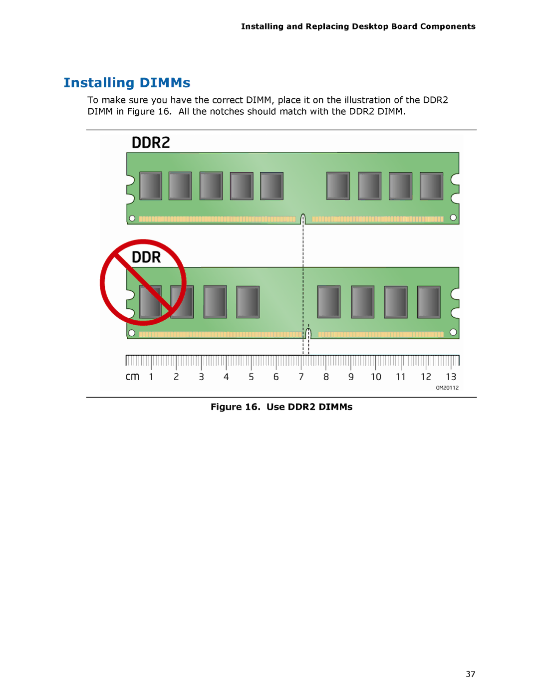
To make sure you have the correct DIMM, place it on the illustration of the DDR2
DIMM in
Figure 16. All the notches should match with the DDR2 DIMM.
Figure 16. Use DDR2 DIMMs
Contents
Main
Revision History
FCC Declaration of Conformity
Canadian Department of Communications Compliance Statement
Disclaimer
Preface
Intended Audience
Use Only for Intended Applications
Document Organization
Conventions
Terminology
Box Contents
Contents
Page
Page
Page
1 Desktop Board Features
Supported Operating Systems
Page
Table 2. Desktop Board DG33TL Components
Processor
Main Memory
Intel G33 Express Chipset
Intel G33 Graphics Subsystem
GMA 3100 Graphics Controller
Digital Video Interface (DVI)
Audio Subsystem
Legacy Input/Output (I/O) Controller
LAN Subsystem
RJ-45 LAN Connector LEDs
Hi-Speed USB 2.0 Support
Enhanced IDE Interface
Serial ATA
Serial ATA RAID
Expandability
BIOS
Serial ATA and IDE Auto Configuration
Hardware Management Features
Hardware Monitoring and Fan Speed Control
Chassis Intrusion
Power Management Features
ACPI
Hardware Support
Power Connectors
Fan Headers
LAN Wake Capabilities
CAUTION
Instantly Available PC Technology
CAUTIONS
+5 V Standby Power Indicator LED
Wake from USB
PME# Signal Wake-up Support
WAKE# Signal Wake-up Support
ENERGY STAR* Qualified
Speaker
Battery
Real-Time Clock
2 Installing and Replacing Desktop Board Components
Before You Begin
CAUTIONS
Installation Precautions
Prevent Power Supply Overload
Observe Safety and Regulatory Requirements
Installing the I/O Shield
Installing and Removing the Desktop Board
Installing and Removing a Processor
Installing a Processor
Page
Page
Installing the Processor Fan Heat Sink
Connecting the Processor Fan Heat Sink Cable
Removing the Processor
Installing and Removing Memory
Guidelines for Dual Channel Memory Configuration
Two or Four DIMMs
Three DIMMs
Page
Page
Removing DIMMs
Installing and Removing a PCI Express x16 Card
Installing a PCI Express x16 Card
Removing the PCI Express x16 Card
Connecting the IDE Cable
Page
Connecting the Serial ATA (SATA) Cables
Installing the External Serial ATA Adapter Bracket
Connecting to the Internal Headers
Connecting to the HD Audio Link Header
Connecting to the IEEE 1394a Header
Installing a Front Panel Audio Solution for Intel High Definition Audio
Connecting to the Consumer IR (CIR) Headers
Connecting to the Serial Port Header
Connecting to the Chassis Intrusion Header
Connecting to the Alternate Front Panel Power LED Header
Connecting to the Front Panel Header
Connecting to the USB 2.0 Headers
Connecting to the Flexible Audio System
Page
Connecting Supply Power Cables
Setting the BIOS Configuration Jumper
Table 15. Jumper Settings for the BIOS Setup Program Modes
Clearing Passwords
Replacing the Battery
CAUTION
PRECAUTION
FORHOLDSREGEL
OBS!
Page
Page
UYARI
O
Page
Page
3 Updating the BIOS
Updating the BIOS with the Intel Express BIOS Update Utility
Updating the BIOS with the ISO Image BIOS Update File or the Iflash Memory Update Utility
Obtaining the BIOS Update File
Updating the BIOS with the ISO Image BIOS Update File
Updating the BIOS with the Iflash Memory Update Utility
Recovering the BIOS
4 Configuring for RAID (Intel Matrix Storage Technology)
Configuring the BIOS for Intel Matrix Storage Technology
Creating Your RAID Set
Loading the Intel Matrix Storage Technology RAID Drivers and Software
Setting Up a RAID Ready System
A Error Messages and Indicators
BIOS Beep Codes
BIOS Error Messages
Page
B Regulatory Compliance
Safety Regulations
Place Battery Marking
European Union Declaration of Conformity Statement
Page
Product Ecology Statements
Recycling Considerations
Page
Lead-Free Desktop Board
Table 19. Lead-Free Board Markings
EMC Regulations
Ensure Electromagnetic Compatibility (EMC) Compliance
Product Certifications
Board-Level Certification Markings
Chassis and Component Certifications