USER’S Manual
Table of Content
Appendix
Item Checklist
Installing the motherboard to the chassis…
Features Summary
Introduction
Bios
GA-4MXSV Motherboard Layout
G H
Intel 82573V GbE
Hardware Installation Process
Step
Installing Processor and CPU Haet Sink
Installing CPU
Installing Heat Sink
Install memory modules
Installation Steps
Install expansion cards
Connect ribbon cables, cabinet wires, and power supply
I/O Back Panel Introduction
LAN LED Description
Connectors & Jumper Setting Introduction
ATX ATX Power Connector
ATX12V +12V Power Connector
IDE1 IDE Connector
FDC1 Floppy Connector
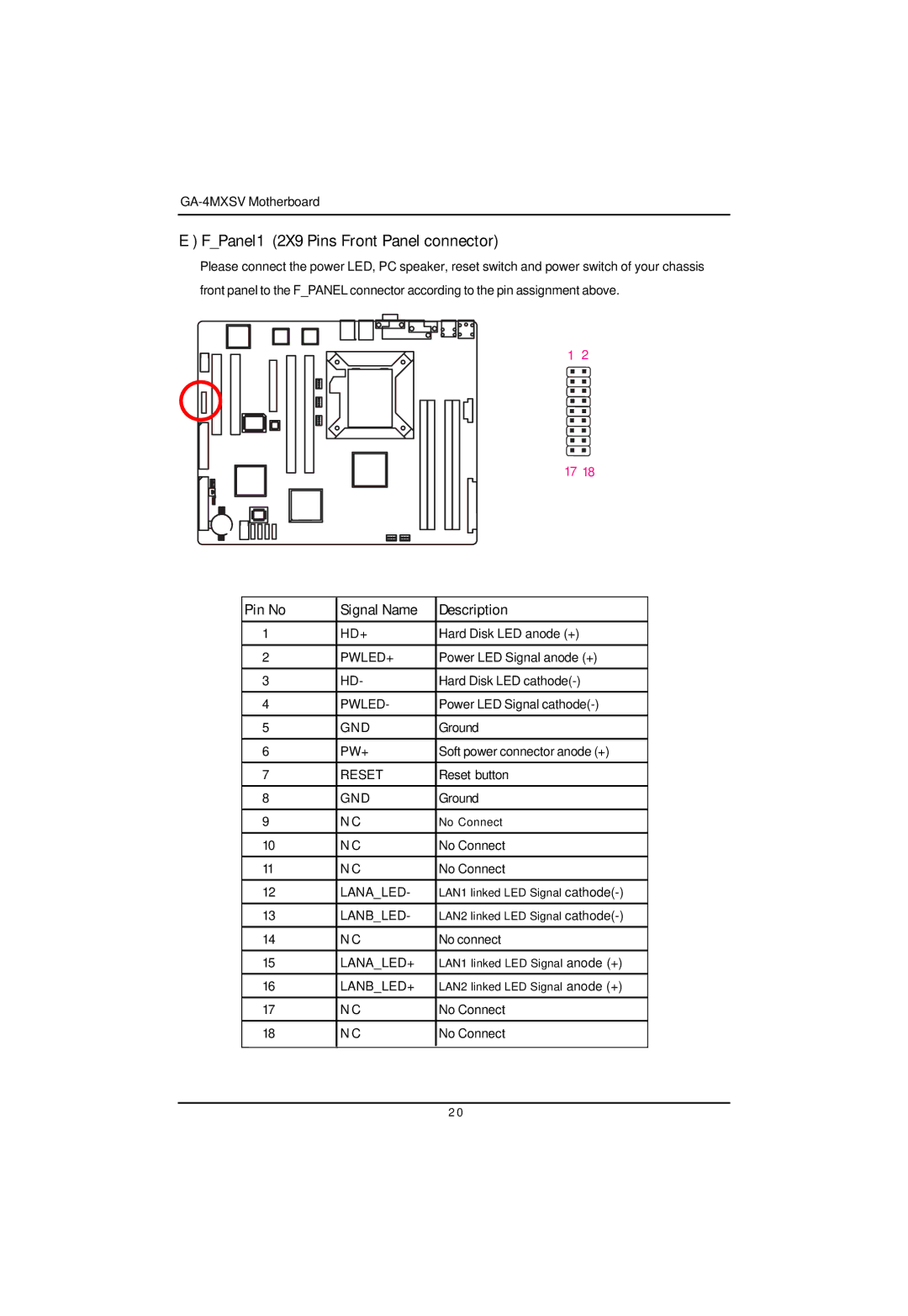
FPanel1 2X9 Pins Front Panel connector
Pin No Signal Name Description
USB2 Front USB Connector
COM2
J / K SATA1/ 2/ 3/ 4 Serial ATA Connectors
WOL1 Wake on LAN
UF1 CPU Fan Connector
WOR1 Wake on Ring
Q / R UF2/3/4/5 System Fan Connectors
Clrcmos Clear Cmos Function
Recovery Bios Recovery Function
Please remove the jumper when system reboot next time
BAT1 Battery
Bios Setup
Status Page Setup Menu / Option Page Setup Menu
Boot
MainMenu
Main
System Time
System Date
Hard Disk Pre-Delay
Legacy Diskette A/B
Bit I/O
Type
Advanced Processor Option
Processor Reset
Advanced Processor Options
Processor Power Management
C1 Enhanced Mode
No Execute Mode Mem. Protection
Advanced
About This Section Advanced
Memory Configuration
Installed Memory/Available to OS/DIMMGroup 1,2,3,4 Status
Memory Reset
Extend RAM Step
PCI Configuration
EmbeddedNIC#1
Onboard LAN1 Control
Option ROM Scan
Enabled
PCI Slot 1/2/3/4/5 Option ROM
Device Configuration
I/O Device Configuration
Serial Port a
Serial Port B
USB Controller
Parallel Port
PS/2 Mouse
USB 2.0 Controller
Legacy USB Support
Route Port 80h cycles to
Parallel ATA
` Native Mode Operation
` Sata Controller Mode Option
` Sata Ahci Enable
` Sata RAID Enable
Enable MultimediaTimer
Advanced Chipset Control
PCI Express Sub-Menu
PCIDevice
Wake On Ring
Wake On RTC Alarm
Wake On LAN / PME
CPU / Motherboard/AmbitTemperature
This Menu will disappear when BMC module is populated
Hardware Monitor
Voltage Monitor 3V Dual, VCC3, VCC, 12V2, 12V1, VBAT, 5VSB
Boot -time Diagnostic
Reset ConfigurationData
Memory Processor Error
Multiprocessor Specification
Set User Password
About This Section Security
Set Supervisor Password
Password on boot
Fixed disk boot sector
Diskette access
Server
System Management
Server Management
Bios Redirection Port
Console Redirection
Baud Rate
TerminalType
FlowControl
Console Connect
Continue C.R. after Post
EventLogConfuguration
Post Error Pause
Mini BMC Function
Mini BMC SEL View
Log Post System Event
Event Log Viewer
System Fan 1/2/3/4/5/6 Error
Voltage Error
BTemperature Error
Set Threshold
Key used to view ot configure devices
About This Section Boot
Boot Priority Order
Exit
About This Section Exit
Exit Saving Changes
Exit Discarding Changes
Load SettupDefault
Discard Changes
Save Changes
Technical Reference
Intel Chipset Software Installation Utilities
Installation Procedures
Auto Run window Setup Wizard
License Aggremment
Installation Completed
Auto Run window Intel LAN Drivers
Intel LAN Driver Installation
Installation Wizard License Agreement
Installation Complete
Install Option Start Installation
Installation Progress
Starting make a driver disk
Intel Host RAID Driver Installation
Auto Run window Host RAID Driver
Formatting and writing in floppy sidk
VGA ES1000 Driver Installation
License Aggremment Installation Complete
DirectX 9.0 Driver Installation
Starting Installaiton
Installaiton Wizard completed
Auto Run window License Agreement
Appendix
Acronyms
Ioapic