Manuals
/
Intel
/
Computer Equipment
/
Computer Hardware
Intel
IB935 Speaker Pins 1, Pin #, Signal Name, Power LED Pins 11, ATX Power ON Switch Pins 7 and
Models:
IB935
1
23
66
66
Download
66 pages
46.84 Kb
20
21
22
23
24
25
26
27
Page 23
Image 23
Page 22
Page 24
Page 23
Image 23
Page 22
Page 24
Contents
USER’S MANUAL
IB935, IB935RF
Version
IB935
Acknowledgments
Realtek HD Code Audio Driver Installation
Installations
BIOS Setup
Drivers Installation
The IB935 CPU Card
INTRODUCTION
Introduction
Product Description
Reminder
Checklist
Specifications
Board Dimensions
INSTALLATIONS
Installations
Installing the CPU
DDR2 Module Lock
Installing the Memory
Lock
Setting the Jumpers
Page
Jumper Locations on IB935
Jumpers on IB935
JP5 Power ON Setting
JP4 Configure and Recovery Factory use only
JP11
JP7 ICH9 PCI-E port 1-4 Configuration Settings
JP11 Clear CMOS Contents
JP7 Setting
Connectors on IB935
Factory use only
Connector Locations on IB935
CN1, CN2, CN3, CN4 SATA HDD Connector
ATX1 ATX 12V Power Connector
CPUFAN1 CPU Fan Power Connector
SYSFAN1, SYSFAN2 SYSTEM Fan Power Connector
FDD1
IDE1 Primary IDE Connector
FDC1 Floppy Drive Connector
IDE1
AutoFeed
VGA1 VGA CRT Connector
J1 External Audio Connector
J2 Parallel Port Connector
J5 CD-In Audio Connector
J3 Digital I/O Connector 4 in, 4 out
J4 IrDA Connector
J7 is a 10-pin header support RS232 COM ports
J7 COM1 Serial Ports Connector
J8 System Function Connector
J6 COM2 Serial Port
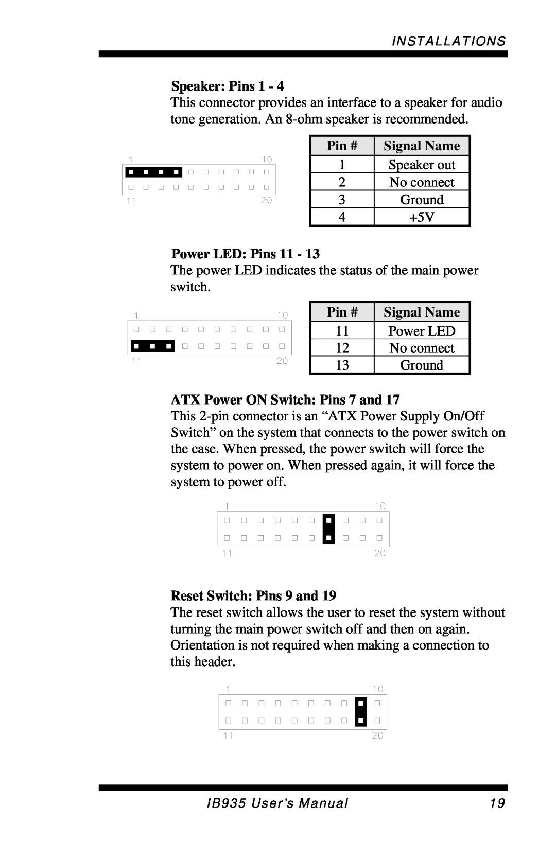
Reset Switch Pins 9 and
Speaker Pins 1
Power LED Pins 11
ATX Power ON Switch Pins 7 and
J12 Wake On LAN Connector
J9 PS/2 Keyboard and Mouse Connector
J10, J11 External PS/2 Mouse and Keyboard Connector
J16 SPI Debug Tools Port Factory use only
J13 USB Connector
J14 USB Connector
J15, J17 Gigabit LAN RJ45 Connector
This page is intentionally left blank
BIOS Setup
Press DEL to Enter Setup
BIOS Introduction
BIOS Setup
Standard CMOS Features
Date
Standard CMOS Setup
Landing Zone Landing zone
Time
IDE Channel Master/Slave
Drive A / Drive B
The system boot will not be halted for any error
Video
Halt On
Quick Power On Self Test
Advanced BIOS Features
CPU Feature
Hard Disk Boot Priority
Boot Up NumLock Status
First/Second/Third Boot Device
Boot Other Device
Boot Up Floppy Seek
OS Select for DRAM 64MB
Security Option
APIC Mode
MPS Version Control for OS
DRAM RAS# to CAS# Delay
Advanced Chipset Features
DRAM Timing Selectable
CAS Latency Time
System Memory Frequency
System BIOS Cacheable
VGA Setting
Precharge delay tRAS
Integrated Peripherals
IDE Primary/Secondary Master/Slave PIO
IDE DMA Transfer Access
IDE HDD Block Mode
OnChip Secondary PCI IDE
LEGACY Mode Support
Power ON Function
KB Power ON Password
Hot Key Power ON
USB 2.0 Controller
Parallel Port Mode
PWRON After PWR-Fail
USB 1.0 Controller
ACPI Suspend
Power Management Setup
Power Management
ACPI Function
Suspend Type
HDD Power Down
Video Off Method
Video Off In Suspend
Reload Global Timer Events
Power On by Ring
Resume by Alarm
Init Display First
PNP/PCI Configurations
PNP OS Installed
Reset Configuration Data
Temperatures/Fan Speeds/Voltages
PC Health Status
Shutdown Temperature
CPU Warning Temperature
Spread Spectrum
Frequency/Voltage Control
Auto Detect PCI Clk
Save & Exit Setup
Load Fail-Safe Defaults
Load Optimized Defaults
Set Supervisor Password
IDE Controller Driver Installation……………………………..52
Drivers Installation
Intel Chipset Software Intallation Utility
2. Click IntelR Chipset Software Installation Utility
6. When the Setup Progress screen appears, click Next to continue
2. Click IntelR Bearlake Chipset Family Graphics Driver
Intel Graphics Driver Installation
2. Click Realtek High Definition Codec Audio Driver
Realtek HD Code Audio Driver Installation
2. Click IntelR PRO LAN Network Drivers
Intel PRO LAN Drivers Installation
1. The BIOS Setup item “Wake-Up by PCI card” has to be set as Enabled
IDE Controller Drivers Installation
A. I/O Port Address Map
Appendix
Level
B. Interrupt Request Lines IRQ
EnableAndSetWatchdog
C. Watchdog Timer Configuration
set count mode as second
Name UnlockChip IN None
Name ReadReg IN CL - register index
D. Digital I/O Sample Code
void LockW627HF void //===================================================================== void UnlockW627HF void
switch to logic device
IB935 User’s Manual
This page is intentionally left blank
APPENDIX
Top
Page
Image
Contents