Contents
Version
Socket LGA775 Pentium Intel 945G Chipset
Industrial Motherboard
MB886
Acknowledgments
Drivers Installation
Installations
BIOS Setup
Introduction
This page is intentionally left blank
INTRODUCTION
Checklist
Introduction
Product Description
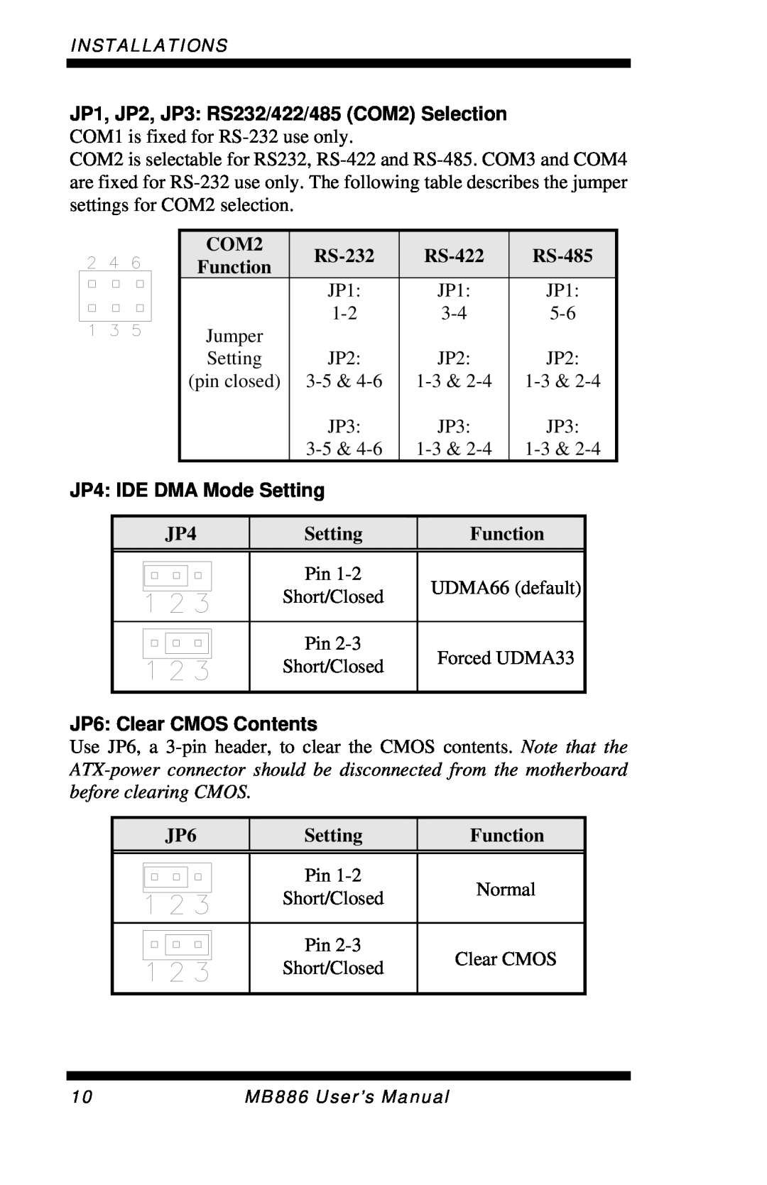
INSTALLATIONS
System
Specifications
MB886
Graphics
Board Dimensions
Installations
Installing the CPU
ATX Power Installation
Installing the Memory
Setting the Jumpers
Jumper Locations on MB886
JP4 IDE DMA Mode Setting
JP6 Clear CMOS Contents
Connectors on MB886
Connector Locations on MB886
Signal Name
ATX1 24-pinATX Power Connector
ATX2 ATX 12V Power Connector
Pin #
CN1 PS/2 Keyboard and PS/2 Mouse Connectors
CN2, J2, J7, J8 COM1/2/3/4 Serial Ports
CN3 Parallel Port Connector
CN4: VGA CRT Connector
CN7 GbE RJ-45and USB2/3 Connector
CN5 Audio Connector
CN6 10/100 RJ-45and USB0/1 Connector
CN11, CN10, CN9, CN8 SATA0/1/2/3 Connector
J6 USB6/USB7 Connector
J1 Digital I/O Connector 4 in, 4 out
J5 USB4/USB5 Connector
J3 Audio Front Header
Speaker Pins
J9 Wake On LAN Connector
J10 System Function Connector
Pin # Signal Name
Reset Switch Pins 9 and
Power LED Pins
ATX Power ON Switch Pins 7 and
Hard Disk Drive LED Connector Pins 10 and
FAN2, FAN3, FAN4 Fan Power Connectors
J11 IrDA Connector
FAN1 CPU Fan Power Connector
PCIE 2, PCIE 3 x1 PCI Express Slots
IDE1 Primary IDE Connectors
PCIE_1: x16 PCI Express Slot
PCI1, PCI2, PCI3, PCI4 PCI Slots SL1 ISA Slot
Watchdog Timer Configuration
SAMPLE CODE
INSTALLATIONS
INSTALLATIONS
INSTALLATIONS
INSTALLATIONS
BIOS Setup
Press DEL to Enter Setup
BIOS Introduction
BIOS Setup
BIOS SETUP
Standard CMOS Setup
Date
Drive A / Drive B
Time
IDE Channel Master/Slave
CYLS
Video
Halt On
Hard Disk Boot Priority
Advanced BIOS Features
CPU Feature
Virus Warning
Boot Other Device
Quick Power On Self Test
First/Second/Third Boot Device
Boot Up Floppy Seek
APIC Mode
Typematic Delay Msec
Security Option
MPS Version Control for OS
CAS Latency Time
Advanced Chipset Features
DRAM Timing Selectable
DRAM RAS# to CAS# Delay
On-ChipVGA Setting
System BIOS Cacheable
Video BIOS Cacheable
DRAM RAS# Precharge
Onboard Device
Integrated Peripherals
OnChip IDE Device
2nd Super IO Device
IDE HDD Block Mode
IDE DMA Transfer Access
On-chipPrimary PCI IDE Enabled
OnChip Primary/Secondary PCI IDE
KB Power ON Password
On-ChipSerial ATA Setting
Power ON Function
Hot Key Power ON
PWRON After PWR-Fail
Onboard Serial Port
UART Mode Select
Power Management
Power Management Setup
RUN VGABIOS if S3 Resume
ACPI Function
Resume by Alarm
HDD Power Down
Power On by Ring
Video Off Method
Reload Global Timer Events
Init Display First
PNP/PCI Configurations
Reset Configuration Data
Resources Controlled by
Temperatures/Voltages
PC Health Status
CPU Warning Temperature
Smart Fan2 Temperature
Auto Detect PCI Clk
Frequency/Voltage Control
CPU Clock Ratio
Spread Spectrum Modulated
Set Supervisor Password
Load Fail-SafeDefaults
Load Optimized Defaults
Save & Exit Setup
Realtek Codec Audio Driver Installation
Drivers Installation
Chipset Software Installation Utility
Intel 945G
Intel 945G Chipset Software Installation Utility
DRIVERS INSTALLATION
Intel 945G Chipset Graphics Driver
Realtek Codec Audio Driver Installation
Intel LAN Drivers Installation
Appendix
A. I/O Port Address Map
B. Interrupt Request Lines IRQ
Level