Manuals
/
Intel
/
Computer Equipment
/
Laptop
Intel
EX-98211 FANLESS CELERON, Pentium M Box PC
manual
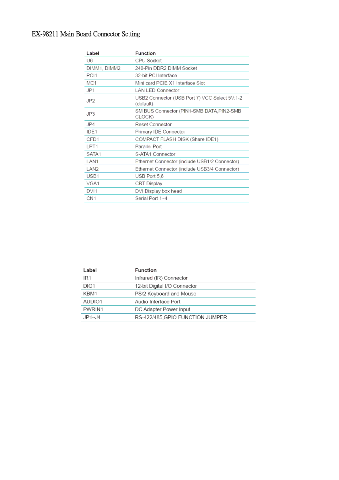
EX-98211 Main Board Connector Setting
Models:
EX-98211 FANLESS CELERON
Pentium M Box PC
1
7
19
19
Download
19 pages
16.5 Kb
4
5
6
7
8
9
10
11
Install
Dimension
Jumpers and Connectors
Page 7
Image 7
EX-98211
Main Board Connector Setting
Page 6
Page 8
Page 7
Image 7
Page 6
Page 8
Contents
EX-98211
Compact-sized
General Information Introduction
System
Packing List
Front View
Power Information I/O Ports Arrangement
Back View
Engine of EX-98211 Introduction
Dimensions
EX-98211 Main Board Bottom View
Jumpers and Connectors
EX-98211 Main Board Connector Setting
JRS1 RS-232/422/485 Selection JP1 LAN LED Connector
IDE1 Primary IDE Connector
SATA1~2 S-ATA1 Connector
LPT1 Parallel Port Connector
CFD1 Compact Flash Disk Share IDE1
USB1 Connector USB Port 5 VGA1 CRT Connector
LAN1/LAN2 Connector USB Port 1, 2 ~ USB Port 3
DVI1 DVI Connector
AUDIO1 Audio Interface Port PWRIN1 DC Adapter Power Input
Remove Top Cover
Hardware Installation
Installing CPU
RS-422/485, Gpio Function Jumper
Page
Installing CF Card
Installing Memory Module
Remove Bottom Cover
Installing Hard Disk Drive
Installing Riser Card
Installing Wall-mount Bracket
Top
Page
Image
Contents