intelligent motion systems, INC.
Excellence in Motion![]()
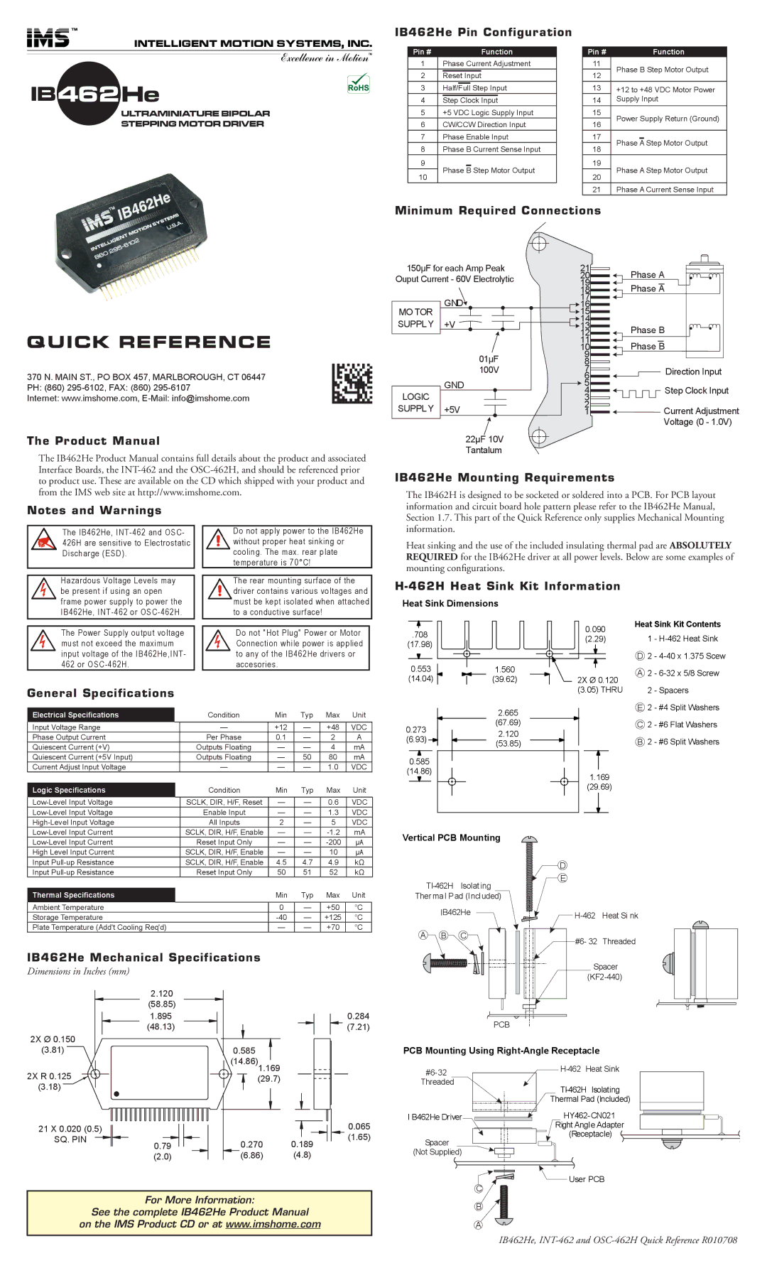
IB462He
ULTRAMINIATURE BIPOLAR
STEPPING MOTOR DRIVER
IB462He Pin Configuration
Pin # | Function |
1Phase Current Adjustment
2Reset Input
3Half/Full Step Input
4Step Clock Input
5+5 VDC Logic Supply Input
6CW/CCW Direction Input
7Phase Enable Input
8Phase B Current Sense Input
9
Phase B Step Motor Output
10
Pin # | Function | |
11 | Phase B Step Motor Output | |
12 | ||
|
13+12 to +48 VDC Motor Power
14Supply Input
15 | Power Supply Return (Ground) | |||
16 | ||||
|
|
| ||
17 |
|
|
| |
Phase A Step Motor Output | ||||
18 | ||||
|
|
| ||
19 | Phase A Step Motor Output | |||
20 | ||||
|
|
| ||
21 | Phase A Current Sense Input | |||
Minimum Required Connections
150µF for each Amp Peak Ouput Current - 60V Electrolytic
21
20
19
18
17
Phase A Phase A
MO TOR
GND
16
15
14
QUICK REFERENCE
370 N. MAIN ST., PO BOX 457, MARLBOROUGH, CT 06447 PH: (860)
Internet: www.imshome.com,
The Product Manual
The IB462He Product Manual contains full details about the product and associated Interface Boards, the
SUPPLY +V
01µF
100V
GND
LOGIC SUPPLY +5V
22µF 10V Tantalum
13
12
11
10
9
8
7
6
5
4
3
2
1
Phase B
Phase B
![]() Direction Input Step Clock Input
Direction Input Step Clock Input
![]()
![]()
![]() Current Adjustment Voltage (0 - 1.0V)
Current Adjustment Voltage (0 - 1.0V)
to product use. These are available on the CD which shipped with your product and from the IMS web site at http://www.imshome.com.
Notes and Warnings
IB462He Mounting Requirements
The IB462H is designed to be socketed or soldered into a PCB. For PCB layout information and circuit board hole pattern please refer to the IB462He Manual, Section 1.7. This part of the Quick Reference only supplies Mechanical Mounting
The IB462He,
Hazardous Voltage Levels may be present if using an open frame power supply to power the IB462He,
The Power Supply output voltage must not exceed the maximum input voltage of the IB462He,INT- 462 or
Do not apply power to the IB462He without proper heat sinking or cooling. The max. rear plate temperature is 70°C!
The rear mounting surface of the driver contains various voltages and must be kept isolated when attached to a conductive surface!
Do not "Hot Plug" Power or Motor Connection while power is applied to any of the IB462He drivers or accesories.
information.
Heat sinking and the use of the included insulating thermal pad are ABSOLUTELY REQUIRED for the IB462He driver at all power levels. Below are some examples of mounting configurations.
H-462H Heat Sink Kit Information
Heat Sink Dimensions
.708 |
| 0.090 | Heat Sink Kit Contents | ||
|
| 1 - | |||
| (2.29) |
| |||
(17.98) |
|
| |||
|
|
|
| ||
|
|
| D 2 - | ||
0.553 | 1.560 |
| A | 2 - | |
(14.04) | (39.62) | 2X Ø 0.120 | |||
|
| ||||
General Specifications
Electrical Specifications |
| Condition | Min | Typ | Max | Unit |
Input Voltage Range |
| — | +12 | — | +48 | VDC |
Phase Output Current |
| Per Phase | 0.1 | — | 2 | A |
Quiescent Current (+V) |
| Outputs Floating | — | — | 4 | mA |
Quiescent Current (+5V Input) |
| Outputs Floating | — | 50 | 80 | mA |
Current Adjust Input Voltage |
| — | — | — | 1.0 | VDC |
|
|
|
|
|
|
|
Logic Specifications |
| Condition | Min | Typ | Max | Unit |
|
|
|
|
|
|
|
| SCLK, DIR, H/F, Reset | — | — | 0.6 | VDC | |
| Enable Input | — | — | 1.3 | VDC | |
| All Inputs | 2 | — | 5 | VDC | |
| SCLK, DIR, H/F, Enable | — | — | mA | ||
| Reset Input Only | — | — | µA | ||
High Level Input Current |
| SCLK, DIR, H/F, Enable | — | — | 10 | µA |
(3.05) THRU | 2 - Spacers |
| 2.665 | E | 2 | - #4 Split Washers | |
|
|
|
| ||
0.273 | (67.69) | C | 2 | - #6 Flat Washers | |
2.120 |
|
|
| ||
(6.93) | B | 2 | - #6 Split Washers | ||
(53.85) | |||||
0.585 |
|
|
|
| |
(14.86) |
| 1.169 |
|
| |
|
|
|
| ||
|
| (29.69) |
|
|
Vertical PCB Mounting
Input | SCLK, DIR, H/F, Enable | 4.5 | 4.7 | 4.9 | kΩ |
Input | Reset Input Only | 50 | 51 | 52 | kΩ |
|
|
|
|
|
|
Thermal Specifications |
| Min | Typ | Max | Unit |
|
|
|
|
|
|
Ambient Temperature |
| 0 | — | +50 | °C |
Storage Temperature |
| — | +125 | °C | |
Plate Temperature (Add't Cooling Req'd) |
| — | — | +70 | °C |
IB462He Mechanical Specifications
Dimensions in Inches (mm)
2.120 |
|
(58.85) |
|
1.895 | 0.284 |
(48.13) | (7.21) |
2X Ø 0.150 |
|
IB462He
A B C
PCB
D
E
#6- 32 Threaded
Spacer
(3.81) | 0.585 |
| (14.86) |
PCB Mounting Using
2X R 0.125 |
| 1.169 |
|
|
| (29.7) |
|
| |
(3.18) |
|
|
|
|
21 X 0.020 (0.5) |
|
|
| 0.065 |
SQ. PIN | 0.79 | 0.270 | 0.189 | (1.65) |
|
| |||
| (2.0) | (6.86) | (4.8) |
|
For More Information:
See the complete IB462He Product Manual
on the IMS Product CD or at www.imshome.com
I B462He Driver
Spacer
(Not Supplied)
Thermal Pad (Included)
HY462- CN021
Right Angle Adapter (Receptacle)
![]() User PCB
User PCB
C
B
A
IB462He,