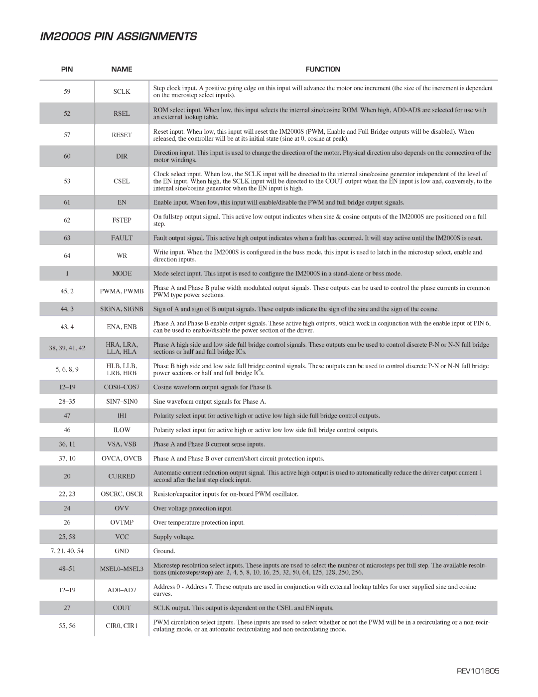
IM2000S PIN ASSIGNMENTS

PIN

NAME

59

SCLK

52

RSEL

57

RESET

60

DIR

53

CSEL

61

EN

62

FSTEP

63

FAULT

64

WR

1

MODE

45, 2

PWMA, PWMB

44, 3

SIGNA, SIGNB

43, 4

ENA, ENB

38, 39, 41, 42

HRA, LRA,

LLA, HLA


5, 6, 8, 9

HLB, LLB,

LRB, HRB


12–19

COS0–COS7

28–35

SIN7–SIN0

47

IHI

46

ILOW

36, 11

VSA, VSB

37, 10

OVCA, OVCB

20

CURRED

22, 23

OSCRC, OSCR

24

OVV

26

OVTMP

25, 58

VCC

7, 21, 40, 54

GND

48–51

MSEL0–MSEL3

12–19

AD0–AD7

27

COUT

55, 56

CIR0, CIR1

FUNCTION

Step clock input. A positive going edge on this input will advance the motor one increment (the size of the increment is dependent on the microstep select inputs).

ROM select input. When low, this input selects the internal sine/cosine ROM. When high, AD0-AD8 are selected for use with an external lookup table.

Reset input. When low, this input will reset the IM2000S (PWM, Enable and Full Bridge outputs will be disabled). When released, the controller will be at its initial state (sine at 0, cosine at peak).

Direction input. This input is used to change the direction of the motor. Physical direction also depends on the connection of the motor windings.

Clock select input. When low, the SCLK input will be directed to the internal sine/cosine generator independent of the level of the EN input. When high, the SCLK input will be directed to the COUT output when the EN input is low and, conversely, to the internal sine/cosine generator when the EN input is high.

Enable input. When low, this input will enable/disable the PWM and full bridge output signals.

On fullstep output signal. This active low output indicates when sine & cosine outputs of the IM2000S are positioned on a full step.

Fault output signal. This active high output indicates when a fault has occurred. It will stay active until the IM2000S is reset.

Write input. When the IM2000S is configured in the buss mode, this input is used to latch in the microstep select, enable and direction inputs.

Mode select input. This input is used to configure the IM2000S in a stand-alone or buss mode.

Phase A and Phase B pulse width modulated output signals. These outputs can be used to control the phase currents in common PWM type power sections.

Sign of A and sign of B output signals. These outputs indicate the sign of the sine and the sign of the cosine.

Phase A and Phase B enable output signals. These active high outputs, which work in conjunction with the enable input of PIN 6, can be used to enable/disable the power section of the driver.

Phase A high side and low side full bridge control signals. These outputs can be used to control discrete P-N or N-N full bridge sections or half and full bridge ICs.

Phase B high side and low side full bridge control signals. These outputs can be used to control discrete P-N or N-N full bridge power sections or half and full bridge ICs.

Cosine waveform output signals for Phase B.

Sine waveform output signals for Phase A.

Polarity select input for active high or active low high side full bridge control outputs.

Polarity select input for active high or active low low side full bridge control outputs.

Phase A and Phase B current sense inputs.

Phase A and Phase B over current/short circuit protection inputs.

Automatic current reduction output signal. This active high output is used to automatically reduce the driver output current 1 second after the last step clock input.

Resistor/capacitor inputs for on-board PWM oscillator.

Over voltage protection input.

Over temperature protection input.

Supply voltage.

Ground.

Microstep resolution select inputs. These inputs are used to select the number of microsteps per full step. The available resolu- tions (microsteps/step) are: 2, 4, 5, 8, 10, 16, 25, 32, 50, 64, 125, 128, 250, 256.

Address 0 - Address 7. These outputs are used in conjunction with external lookup tables for user supplied sine and cosine curves.

SCLK output. This output is dependent on the CSEL and EN inputs.

PWM circulation select inputs. These inputs are used to select whether or not the PWM will be in a recirculating or a non-recir- culating mode, or an automatic recirculating and non-recirculating mode.

REV101805

Page 2
Image 2
Intelligent Motion Systems dimensions IM2000S PIN Assignments

IM2000S specifications

The Intelligent Motion Systems IM2000S is an advanced motion control system designed to meet the demands of various industrial applications. It integrates cutting-edge technology with user-friendly features to provide precise control, efficiency, and flexibility, making it ideal for automation in manufacturing, robotics, and related fields.

One of the standout features of the IM2000S is its high-performance motion control capability. It supports multiple axes of simultaneous control, enabling complex motion profiles to be executed with ease. The system is designed to handle both high-speed and high-precision tasks, offering a resolution of up to microns. This precision allows it to be utilized in applications such as CNC machining, packaging, and material handling, where accurate positioning is critical.

Another significant characteristic of the IM2000S is its robust connectivity options. The system supports a range of communication protocols, including Ethernet, USB, and fieldbus technologies like CANopen and EtherCAT. This versatility ensures seamless integration into existing automation environments, allowing users to communicate with other devices and systems effectively.

The IM2000S also boasts advanced feedback mechanisms. It uses a combination of encoders and sensors to continually monitor position and velocity, ensuring real-time adjustments are made to maintain optimal performance. This closed-loop control maximizes system reliability and reduces the likelihood of errors or deviations during operation.

Furthermore, the IM2000S features intuitive software for motion programming and control. The accompanying user interface is designed to simplify the programming process, allowing users to develop complex motion sequences without requiring extensive expertise in motion control. The system also includes diagnostic tools to facilitate troubleshooting and performance monitoring, contributing to overall system maintenance and reliability.

In addition to its technological innovations, the IM2000S is built for durability and longevity. Its rugged design and high-quality components make it suitable for harsh industrial environments. The system is engineered to withstand temperature fluctuations, dust, and vibration, ensuring consistent performance over time.

In summary, the Intelligent Motion Systems IM2000S stands out due to its high-performance capabilities, flexible connectivity options, advanced feedback mechanisms, user-friendly software, and robust design. It is an ideal solution for industries seeking to enhance their automation processes, achieve higher precision, and improve overall operational efficiency. The IM2000S represents a significant step forward in motion control technology, catering to the evolving needs of modern manufacturing and robotics.