6. | Reinstall locknut onto pivot bolt. DO NOT tighten. |
7. | Install the provided mounting screw through the lower |
| hole on the front cylinder section of the I.V. holder and |
2.Adjust I.V. Rod to desired height.
3.Securely tighten adjustment knob.
| into the side frame. |
8. | Install locknut onto mounting screw. |
9. | Turn locknut until snug fit is obtained. DO NOT tighten. |
10. | Reinstall the arm to ensure proper fit. Refer to RE- |
| MOVING/INSTALLING THE ARMRESTS in this in- |
| struction sheet. |
11. | Securely tighten both locknuts of STEPS 6 AND 9. |
12. | Install the I. V. rod support tube. Refer to INSTALL- |
| ING THE I.V. ROD SUPPORT TUBE in this instruc- |
| tion sheet. |
INSTALLING THE I.V. ROD SUPPORT TUBE (FIGURE 2)
NOTE: Refer to INSTALLATION WARNINGS in the SAFETY SUMMARY in this instruction sheet.
NOTE: The I.V. holder must already be mounted to the side frame of the wheelchair.
1.Insert the I.V. rod support tube into the rear cylinder of the I.V. rod holder.
NOTE: When installing the I.V. rod support tube, ensure the adjustment knob is pointing out away from the wheel- chair.
2. Turn the I.V. rod support tube until the holes in the I.V. |
rod support tube align with the holes in the rear cylin- |
der of the I.V. rod holder. |
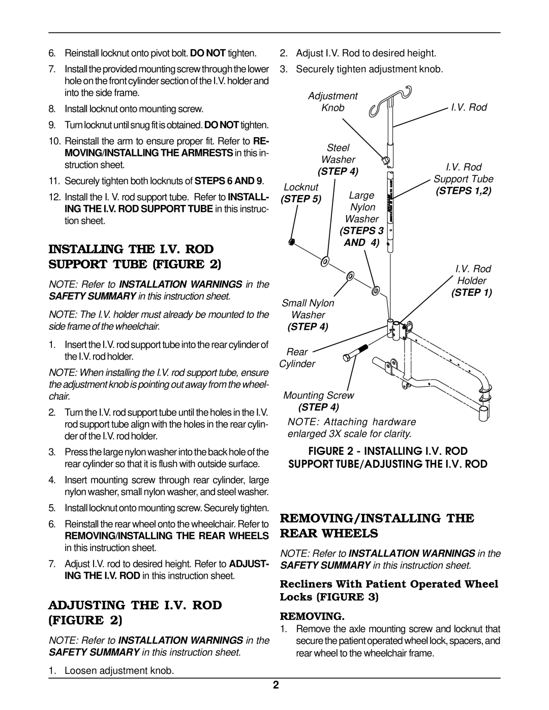
Adjustment
Knob
Steel
Washer
(STEP 4)
Locknut
(STEP 5) | Large | |
Nylon | ||
| ||
| Washer | |
| (STEPS 3 | |
| AND 4) |
Small Nylon
Washer
(STEP 4)
Rear
Cylinder
Mounting Screw
(STEP 4)
NOTE: Attaching hardware enlarged 3X scale for clarity.
I.V. Rod
I.V. Rod
Support Tube
(STEPS 1,2)
I.V. Rod
Holder
(STEP 1)
3. | Press the large nylon washer into the back hole of the |
| rear cylinder so that it is flush with outside surface. |
4. | Insert mounting screw through rear cylinder, large |
| nylon washer, small nylon washer, and steel washer. |
5. | Install locknut onto mounting screw. Securely tighten. |
6. | Reinstall the rear wheel onto the wheelchair. Refer to |
| REMOVING/INSTALLING THE REAR WHEELS |
| in this instruction sheet. |
7. | Adjust I.V. rod to desired height. Refer to ADJUST- |
| ING THE I.V. ROD in this instruction sheet. |
ADJUSTING THE I.V. ROD (FIGURE 2)
NOTE: Refer to INSTALLATION WARNINGS in the SAFETY SUMMARY in this instruction sheet.
1. Loosen adjustment knob.
FIGURE 2 - INSTALLING I.V. ROD
SUPPORT TUBE/ADJUSTING THE I.V. ROD
REMOVING/INSTALLING THE REAR WHEELS
NOTE: Refer to INSTALLATION WARNINGS in the
SAFETY SUMMARY in this instruction sheet.
Recliners With Patient Operated Wheel Locks (FIGURE 3)
REMOVING.
1.Remove the axle mounting screw and locknut that secure the patient operated wheel lock, spacers, and rear wheel to the wheelchair frame.
2