INSTALLING THE TELESCOPING I.V. ROD HOLDER - 2000, 4000 AND 9000 RIDELITE (FIGURE 6)
NOTE: Refer to INSTALLATION WARNINGS in the SAFETY SUMMARY in this instruction sheet.
1.Remove the rear wheel from the wheelchair. Refer to
REMOVING/INSTALLING THE REAR WHEELS in this instruction sheet.
2.Remove the arm from the wheelchair. Refer to RE- MOVING/INSTALLING THE ARMRESTS in this in- struction sheet.
3.Do one (1) of the following:
A.If arm tube does NOT contain arm release lever, proceed to STEP 4.
B.If arm tube contains arm release lever, the spring button and arm release lever MUST be removed to ensure proper fit by performing the following:
a.Depress the spring button on the arm.
b.Slide the arm release lever to remove from the arm.
c.Remove the plug button on the bottom of the arm.
d.Depress the spring button on the arm.
e.Remove the spring from the arm.
f.Reinstall EXISTING plug button to the bottom of the arm.
g.Proceed to STEP 4.
4.Remove the EXISTING pivot bolt and locknut that se- cure the reclining back tube to the rear upright.
5.Install the NEW pivot bolt through the reclining back tube and rear upright.
NOTE: The I.V. rod holder can be mounted on either side of the wheelchair.
NOTE: When installing the I.V. rod support tube, en- sure the adjustment knob is pointing out away from the wheelchair.
8.Install the I.V. rod support tube into the I.V. rod holder.
9.Align the holes in the I.V. rod support tube with the I.V. rod holder.
10.Install the mounting screw through the I.V. holder and I.V. support rod support tube.
11.Install the locknut that secures the I.V. rod sup- port tube and I.V. rod holder to the wheelchair.
12.Reinstall the arm to ensure proper fit. Refer to RE- MOVING/INSTALLING THE ARMRESTS in this in- struction sheet.
13.Securely tighten both locknuts of STEPS 5 AND 8.
14.Reinstall the rear wheel onto the wheelchair. Re- fer to REMOVING/INSTALLING THE REAR WHEELS in this instruction sheet.
15.Adjust I.V. rod to desired height. Refer to ADJUST- ING THE I.V. ROD in this instruction sheet.
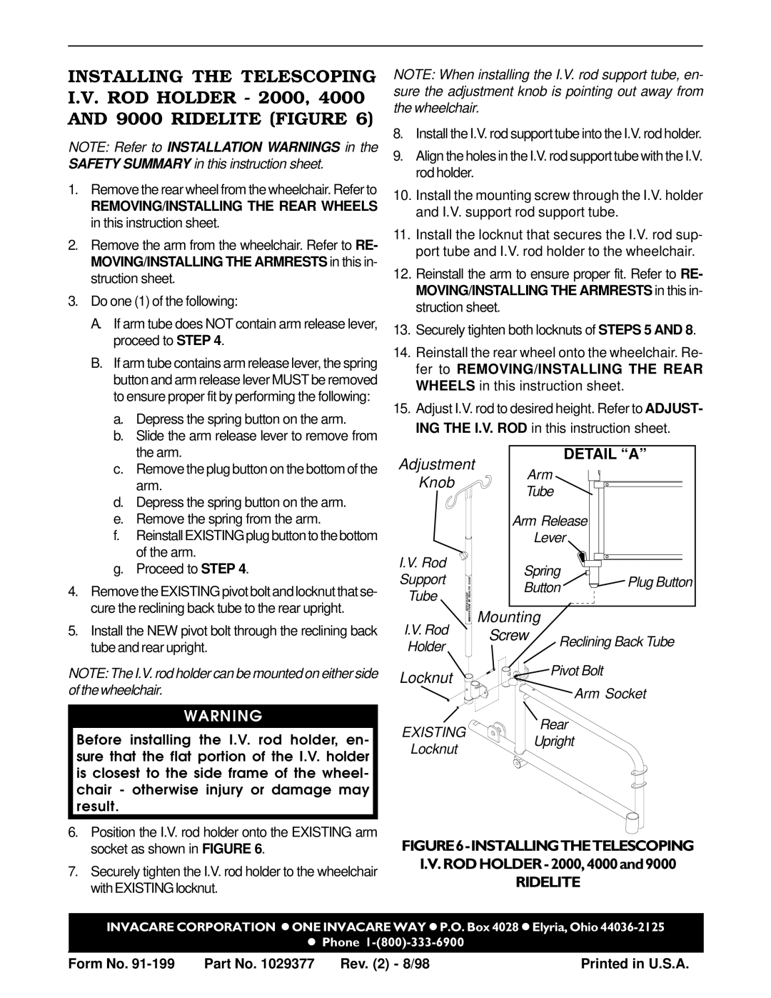
Adjustment
Knob
I.V. Rod
Support
Tube
DETAIL “A”
Arm
Tube
Arm Release
Lever
Spring | Plug Button | |
Button | ||
|
Mounting
I.V. Rod Screw Reclining Back Tube Holder
Locknut | Pivot Bolt | |
Arm Socket | ||
|
WARNING
EXISTING
Rear
Before installing the I.V. rod holder, en- sure that the flat portion of the I.V. holder is closest to the side frame of the wheel- chair - otherwise injury or damage may result.
Locknut
Upright
6.Position the I.V. rod holder onto the EXISTING arm socket as shown in FIGURE 6.
7.Securely tighten the I.V. rod holder to the wheelchair with EXISTING locknut.
FIGURE6-INSTALLINGTHETELESCOPING
RIDELITE
INVACARE CORPORATION lONE INVACARE WAY lP.O. Box 4028 lElyria, Ohio
l Phone
Form No. | Part No. 1029377 | Rev. (2) - 8/98 | Printed in U.S.A. |