FOOTRESTS | PROCEDURE 1 |
This Procedure includes the following:
Swingaway Footrest Assembly Installation
Swingaway Footrest Height Adjustment
Heel Loop Replacement
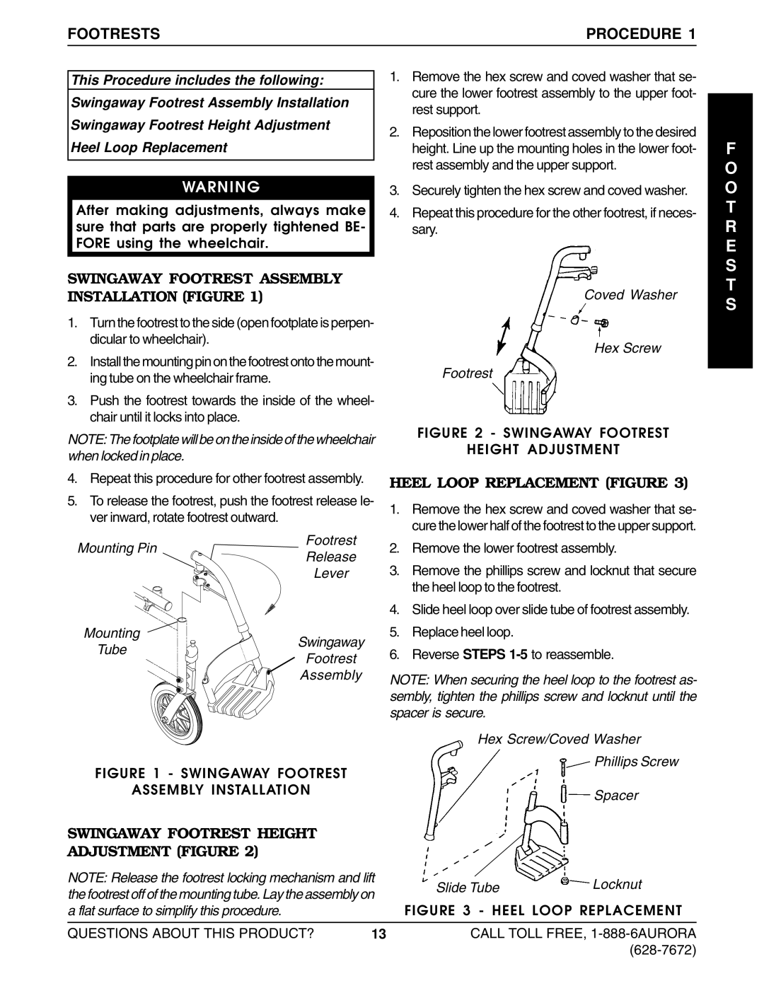
1.Remove the hex screw and coved washer that se- cure the lower footrest assembly to the upper foot- rest support.
2.Reposition the lower footrest assembly to the desired height. Line up the mounting holes in the lower foot- rest assembly and the upper support.
F
O
WARNING
After making adjustments, always make sure that parts are properly tightened BE- FORE using the wheelchair.
SWINGAWAY FOOTREST ASSEMBLY INSTALLATION (FIGURE 1)
1.Turn the footrest to the side (open footplate is perpen- dicular to wheelchair).
2.Install the mounting pin on the footrest onto the mount- ing tube on the wheelchair frame.
3.Push the footrest towards the inside of the wheel- chair until it locks into place.
NOTE: The footplate will be on the inside of the wheelchair when locked in place.
4.Repeat this procedure for other footrest assembly.
5.To release the footrest, push the footrest release le- ver inward, rotate footrest outward.
3.Securely tighten the hex screw and coved washer.
4.Repeat this procedure for the other footrest, if neces- sary.
Coved Washer
Hex Screw
Footrest
FIGURE 2 - SWINGAWAY FOOTREST
HEIGHT ADJUSTMENT
HEEL LOOP REPLACEMENT (FIGURE 3)
1. Remove the hex screw and coved washer that se- |
cure the lower half of the footrest to the upper support. |
O
T
R E S T S
Mounting Pin
Footrest
Release
Lever
2. | Remove the lower footrest assembly. |
3. | Remove the phillips screw and locknut that secure |
| the heel loop to the footrest. |
4. | Slide heel loop over slide tube of footrest assembly. |
Mounting
Swingaway
Tube
Footrest
Assembly
FIGURE 1 - SWINGAWAY FOOTREST
ASSEMBLY INSTALLATION
5. | Replace heel loop. |
6. | Reverse STEPS |
NOTE: When securing the heel loop to the footrest as- sembly, tighten the phillips screw and locknut until the spacer is secure.
Hex Screw/Coved Washer
Phillips Screw
Spacer
SWINGAWAY FOOTREST HEIGHT
ADJUSTMENT (FIGURE 2)
NOTE: Release the footrest locking mechanism and lift |
|
|
| ||
Slide Tube | Lock | nut | |||
the footrest off of the mounting tube. Lay the assembly on | |||||
| |||||
FIGURE 3 - HEEL LOOP REPLACEMENT | |||||
a flat surface to simplify this procedure. |
| ||||
|
|
|
| ||
QUESTIONS ABOUT THIS PRODUCT? | 13 | CALL TOLL FREE, | |||
|
|
| |||