PROCEDURE 6 |
|
A N T I
T
I
This Procedure Includes the Following:
Installing/Adjusting
Wheel Lock Adjustment
WA R N I N G
After making adjustments, always make sure that parts are properly tight- ened BEFORE using the wheelchair.
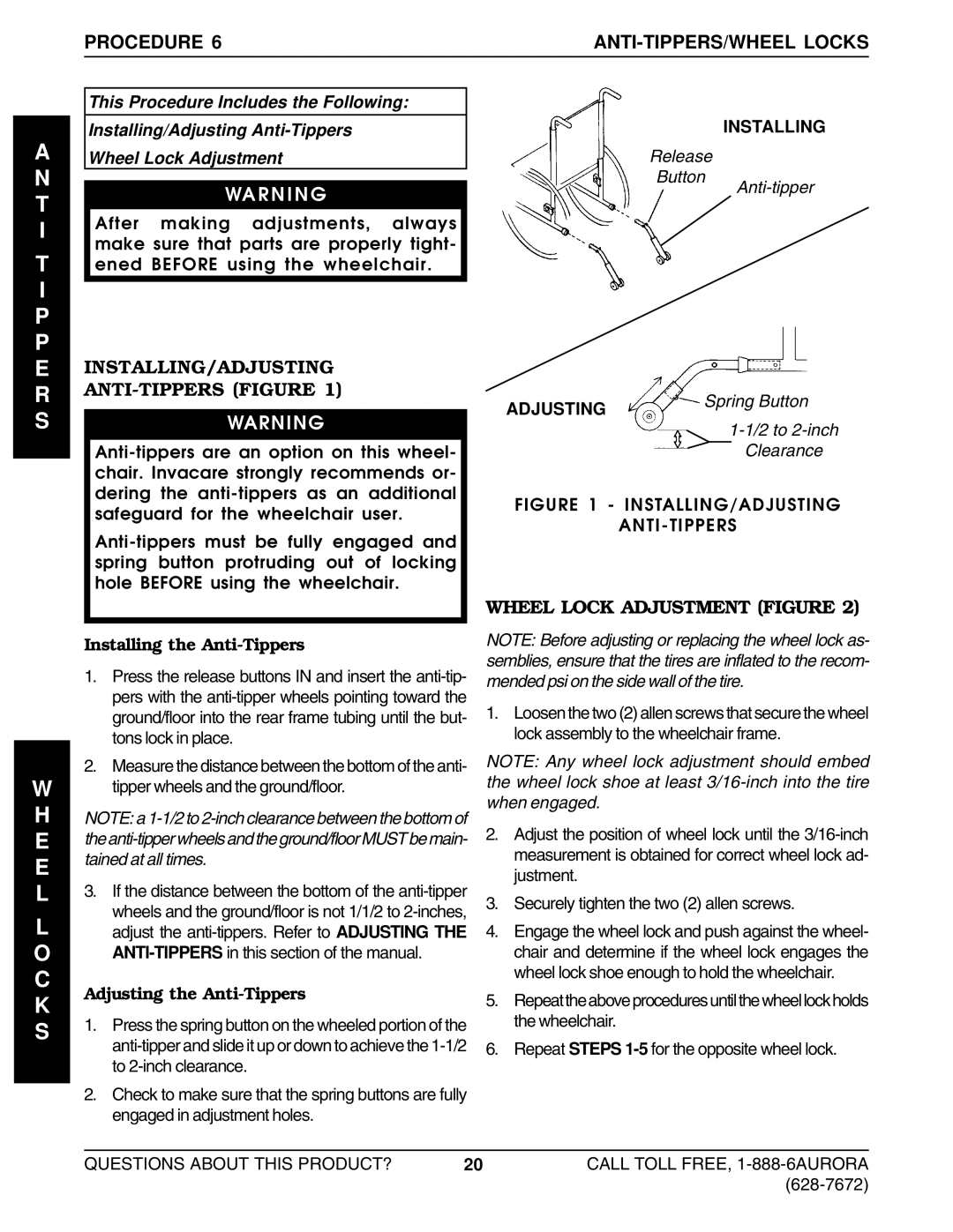
INSTALLING
Release
Button
P P E R S
INSTALLING/ADJUSTING
ANTI-TIPPERS (FIGURE 1)
WARNING
ADJUSTING |
| Spri | ng B | utton | |
|
|
|
| ||
|
|
| |||
|
|
| |||
|
|
|
| Clearance | |
FIGURE 1 - INSTALLING/ADJUSTING
ANTI-TIPPERS
WHEEL LOCK ADJUSTMENT (FIGURE 2)
W
H
E
E
L
L
O C K S
Installing the Anti-Tippers
1.Press the release buttons IN and insert the
2.Measure the distance between the bottom of the anti- tipper wheels and the ground/floor.
NOTE: a
3.If the distance between the bottom of the
Adjusting the Anti-Tippers
1.Press the spring button on the wheeled portion of the
2.Check to make sure that the spring buttons are fully engaged in adjustment holes.
NOTE: Before adjusting or replacing the wheel lock as- semblies, ensure that the tires are inflated to the recom- mended psi on the side wall of the tire.
1.Loosen the two (2) allen screws that secure the wheel lock assembly to the wheelchair frame.
NOTE: Any wheel lock adjustment should embed the wheel lock shoe at least
2.Adjust the position of wheel lock until the
3.Securely tighten the two (2) allen screws.
4.Engage the wheel lock and push against the wheel- chair and determine if the wheel lock engages the wheel lock shoe enough to hold the wheelchair.
5.Repeattheaboveproceduresuntilthewheellockholds the wheelchair.
6.Repeat STEPS
QUESTIONS ABOUT THIS PRODUCT? | 20 | CALL TOLL FREE, |
|
|