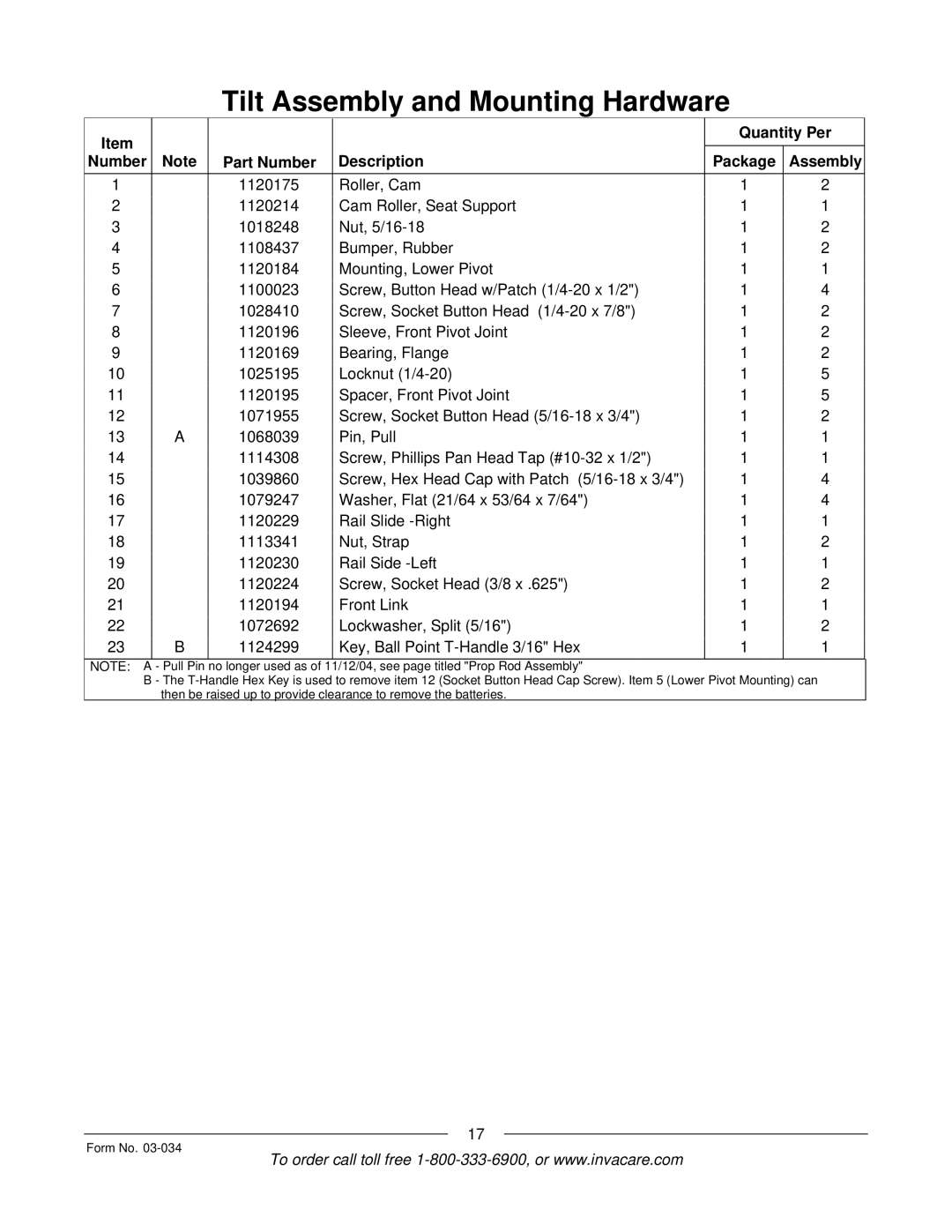
Tilt Assembly and Mounting Hardware
Item | Note | Part Number | Description | Quantity Per |
| |
Number | Package | Assembly |
| |||
1 |
| 1120175 | Roller, Cam | 1 | 2 |
|
2 |
| 1120214 | Cam Roller, Seat Support | 1 | 1 |
|
3 |
| 1018248 | Nut, | 1 | 2 |
|
4 |
| 1108437 | Bumper, Rubber | 1 | 2 |
|
5 |
| 1120184 | Mounting, Lower Pivot | 1 | 1 |
|
6 |
| 1100023 | Screw, Button Head w/Patch | 1 | 4 |
|
7 |
| 1028410 | Screw, Socket Button Head | 1 | 2 |
|
8 |
| 1120196 | Sleeve, Front Pivot Joint | 1 | 2 |
|
9 |
| 1120169 | Bearing, Flange | 1 | 2 |
|
10 |
| 1025195 | Locknut | 1 | 5 |
|
11 |
| 1120195 | Spacer, Front Pivot Joint | 1 | 5 |
|
12 |
| 1071955 | Screw, Socket Button Head | 1 | 2 |
|
13 | A | 1068039 | Pin, Pull | 1 | 1 |
|
14 |
| 1114308 | Screw, Phillips Pan Head Tap | 1 | 1 |
|
15 |
| 1039860 | Screw, Hex Head Cap with Patch | 1 | 4 |
|
16 |
| 1079247 | Washer, Flat (21/64 x 53/64 x 7/64") | 1 | 4 |
|
17 |
| 1120229 | Rail Slide | 1 | 1 |
|
18 |
| 1113341 | Nut, Strap | 1 | 2 |
|
19 |
| 1120230 | Rail Side | 1 | 1 |
|
20 |
| 1120224 | Screw, Socket Head (3/8 x .625") | 1 | 2 |
|
21 |
| 1120194 | Front Link | 1 | 1 |
|
22 |
| 1072692 | Lockwasher, Split (5/16") | 1 | 2 |
|
23 | B | 1124299 | Key, Ball Point | 1 | 1 |
|
NOTE: A - Pull Pin no longer used as of 11/12/04, see page titled "Prop Rod Assembly"
B The
Form No.
17
To order call toll free
