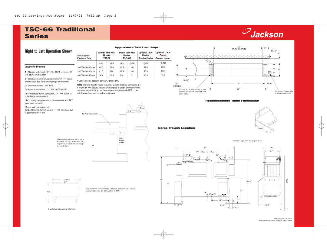
TSC-66 specifications
The Jackson TSC-66, TS-66, TSC-44, TS-44, and TS-44GP are a line of versatile, high-performance scorers designed to meet the diverse needs of any construction or road maintenance crew. Known for their reliability and exceptional build quality, these machines have become trusted tools in various applications, from road construction to surface maintenance.Starting with the TSC-66, it stands as a powerful tool equipped with a robust engine that delivers high-performance results even under demanding conditions. The primary feature is its adjustable cutting depth, allowing operators to customize the depth of the cut based on the project requirements. Additionally, the TSC-66 comes with a user-friendly interface, featuring intuitive controls that enhance operational efficiency. The mobility of this model is another notable characteristic, thanks to its compact design and durable wheels, facilitating easy transport between job sites.
The TS-66 model shares many features with the TSC-66 but offers enhanced versatility with its multi-function capabilities. This machine can tackle various tasks beyond surface cutting, including grinding and finishing, which makes it an excellent choice for contractors specializing in diverse projects. Its high-torque motor is engineered for prolonged use, and its low-vibration technology ensures comfort during operation.
The TSC-44 and TS-44 models provide similar functionality with a focus on compactness and weight. These machines are perfect for smaller jobs and can easily navigate tight spaces. Equipped with advanced hydraulic systems, they feature superior lifting and cutting capabilities, allowing them to perform effectively in various conditions.
The TS-44GP variant is designed for general-purpose applications, combining the features of its peers with added emphasis on durability and ease of use. Its construction is particularly noteworthy, utilizing heavy-duty materials that ensure a long operational life. The incorporation of advanced safety features across all models underscores Jackson's commitment to user safety, with protective guards and emergency stop mechanisms built into the design.
In summary, the Jackson TSC-66, TS-66, TSC-44, TS-44, and TS-44GP models collectively represent a commitment to quality, performance, and versatility in the scoring equipment market. With their unique features, advanced technology, and durable construction, these machines are engineered to excel in a variety of demanding applications, making them a valuable addition to any contractor’s toolkit.

