Page 4
TM-6760 Series Progressive Scan Shutter Cameras
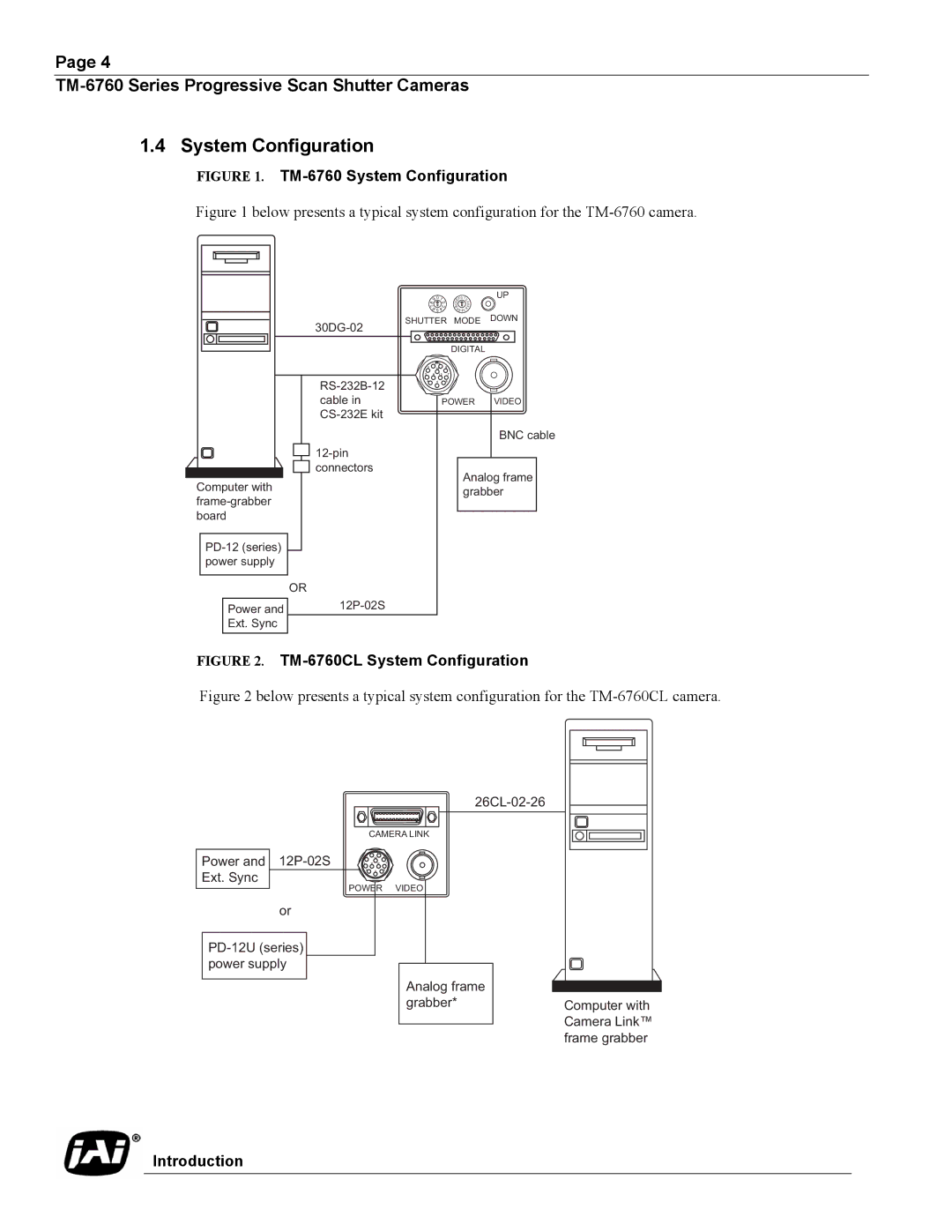
1.4 System Configuration
FIGURE 1. TM-6760 System Configuration
Figure 1 below presents a typical system configuration for the TM-6760 camera.
8 | 9 | 01 | |
| 2 | ||
|
| 3 | |
7 |
| ||
| 6 | ||
| 4 | ||
|
| 5 |
|
F0 CDE
B
A 98
12 |
|
3 | |
| 4 |
76 | 5 |
| |
UP
SHUTTER MODE DOWN
DIGITAL
Computer with
Power and
Ext. Sync
![]()
![]()
![]() connectors
connectors
OR
1 9
2 10 8
3 11 12 7
4 5 6
POWER VIDEO
BNC cable
Analog frame grabber
FIGURE 2. TM-6760CL System Configuration
Figure 2 below presents a typical system configuration for the TM-6760CL camera.
CAMERA LINK
|
|
| 1 | 9 |
|
Power and |
|
| 2 | 10 | 8 |
3 | 11 | 12 | 7 | ||
|
|
| 4 | 5 | 6 |
Ext. Sync |
|
|
|
|
|
|
| POWER | VIDEO | ||
| or |
|
|
|
|
Analog frame
grabber*Computer with Camera Link™ frame grabber