Figure 15. Woofer and tweeter mounted in the kick panel and aimed at a point between the driver and passenger. Coverage provided by separate listening windows.
SYSTEM DESIGN USING THE GTi COMPETITION SPEAKER SYSTEMS.
Many speaker systems are designed for
LISTENING WINDOWS AND MOUNTING LOCATIONS: CHOOSING THE BEST MOUNTING LOCATION AND AIMING THE TWEETER
Using the waveguides and planning your installation carefully will help to provide the best performance from your GTi competition speaker system. Consider the illustrations that follow and the ones to the left, when determining the best mounting locations for your woofers and tweeters.
Figure 16. Woofer mounted in the kick panel and tweeter mounted in the A-pillar and aimed at a point between the driver and passenger. Coverage provided by separate listening windows.
Figure 17. Woofer mounted in the door and waveguide mounted in the kick panel or A-pillar. Woofer aimed across the car, and tweeter aimed at a point between the driver and passenger. Woofer coverage provided by a single window. Tweeter coverage provided by separate
| 65° |
|
|
| 35° |
|
|
- 65° |
|
|
|
5° |
|
| |
| 65° | ||
| 5° | 35° | |
|
|
| |
|
|
| |
0° | - 65° |
| Design Axis |
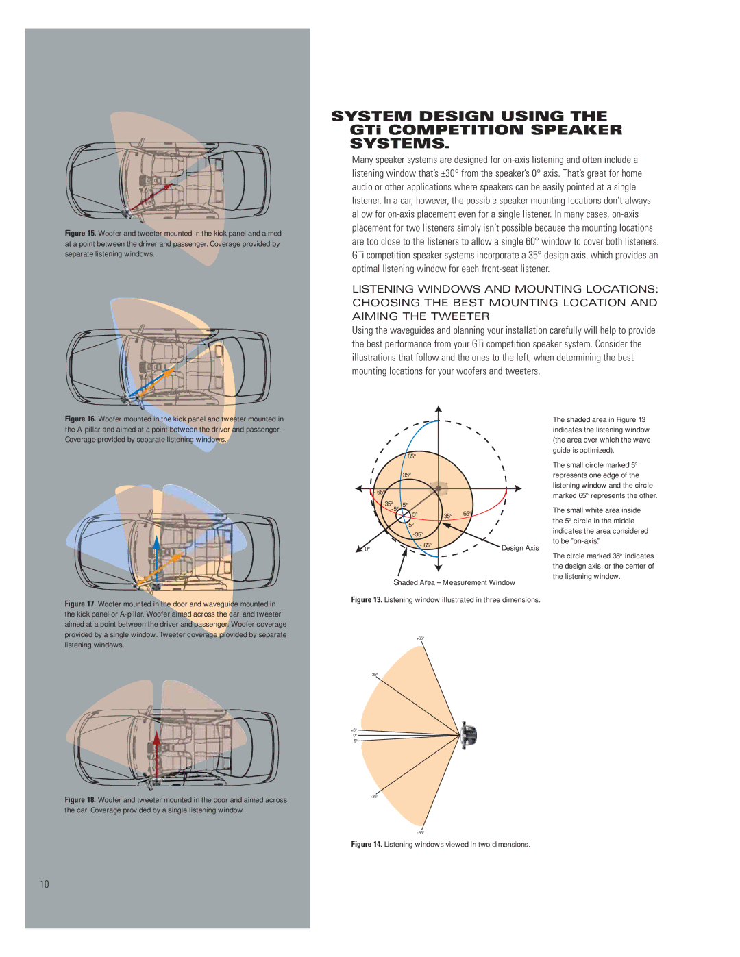
Shaded Area = Measurement Window Figure 13. Listening window illustrated in three dimensions.
The shaded area in Figure 13 indicates the listening window (the area over which the wave- guide is optimized).
The small circle marked 5° represents one edge of the listening window and the circle marked 65° represents the other.
The small white area inside the 5° circle in the middle indicates the area considered to be
The circle marked 35° indicates the design axis, or the center of the listening window.
listening windows.
Figure 18. Woofer and tweeter mounted in the door and aimed across the car. Coverage provided by a single listening window.
+65°
+35°
+5°
0°
Figure 14. Listening windows viewed in two dimensions.
10