|
| |
| Polypropylene | Precision Resistors |
Air Core Coils | Caps | With Integral Heatsink |
the tweeter’s output at low frequencies in the listening window and decreases its out- put in the
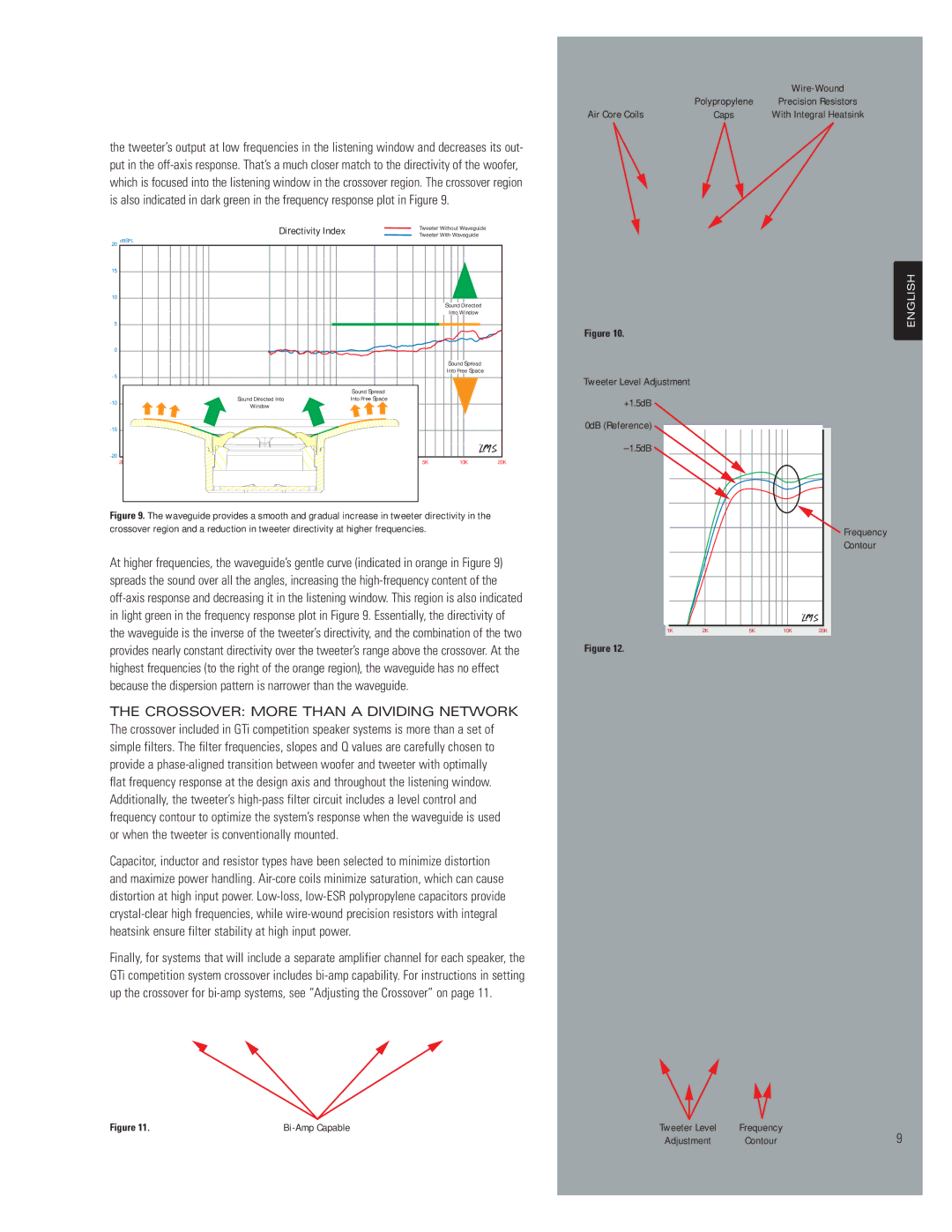
Directivity Index
Tweeter Without Waveguide Tweeter With Waveguide
20 | dBSPL |
|
|
|
|
|
|
|
|
| |
15 |
|
|
|
|
|
|
|
|
| ENGLISH | |
5 |
|
|
|
|
|
|
|
|
| ||
10 |
|
|
|
|
|
|
|
|
|
| |
|
|
|
|
|
|
|
|
| Sound Directed |
| |
|
|
|
|
|
|
|
|
| Into Window |
| |
|
|
|
|
|
|
|
|
|
| Figure 10. | |
0 |
|
|
|
|
|
|
|
|
|
| |
|
|
|
|
|
|
|
|
| Sound Spread |
| |
|
|
|
|
|
|
|
| Into Free Space |
| ||
|
|
|
|
|
|
|
|
| Tweeter Level Adjustment | ||
|
|
|
|
|
|
|
|
|
| ||
|
|
|
|
|
|
| Sound Spread |
|
|
| |
|
|
| Sound Directed Into |
|
| Into Free Space |
|
| +1.5dB | ||
|
|
| Window |
|
|
|
|
| |||
|
|
|
|
|
|
|
|
| 0dB (Reference) | ||
|
|
|
|
|
|
|
|
| |||
20 Hz | 50 | 100 | 200 | 500 | 1K | 2K | 5K | 10K | 20K | ||
|
Figure 9. The waveguide provides a smooth and gradual increase in tweeter directivity in the |
|
|
|
|
|
|
|
|
crossover region and a reduction in tweeter directivity at higher frequencies. |
|
|
|
|
|
|
| Frequency |
|
|
|
|
|
| |||
|
|
|
|
|
|
|
| Contour |
At higher frequencies, the waveguide’s gentle curve (indicated in orange in Figure 9) |
|
|
|
|
|
|
|
|
spreads the sound over all the angles, increasing the |
|
|
|
|
|
|
|
|
|
|
|
|
|
|
|
| |
|
|
|
|
|
|
|
| |
|
|
|
|
|
|
|
| |
in light green in the frequency response plot in Figure 9. Essentially, the directivity of |
|
|
|
|
|
|
|
|
the waveguide is the inverse of the tweeter’s directivity, and the combination of the two |
|
|
|
|
|
|
|
|
1K | 2K | 5K | 10K | 20K | ||||
provides nearly constant directivity over the tweeter’s range above the crossover. At the | Figure 12. |
|
|
|
|
|
| |
highest frequencies (to the right of the orange region), the waveguide has no effect |
|
|
|
|
|
|
|
|
because the dispersion pattern is narrower than the waveguide. |
|
|
|
|
|
|
|
|
THE CROSSOVER: MORE THAN A DIVIDING NETWORK The crossover included in GTi competition speaker systems is more than a set of simple filters. The filter frequencies, slopes and Q values are carefully chosen to provide a
flat frequency response at the design axis and throughout the listening window. Additionally, the tweeter’s
Capacitor, inductor and resistor types have been selected to minimize distortion and maximize power handling.
Finally, for systems that will include a separate amplifier channel for each speaker, the GTi competition system crossover includes
Figure 11. |
| Tweeter Level | Frequency |
Adjustment | Contour | 9 |