SETTING UP THE GTI AMPLIFIER
7.Using a
(see Figure 16 below). Disconnect the ribbon cable from display board.
8.Using a
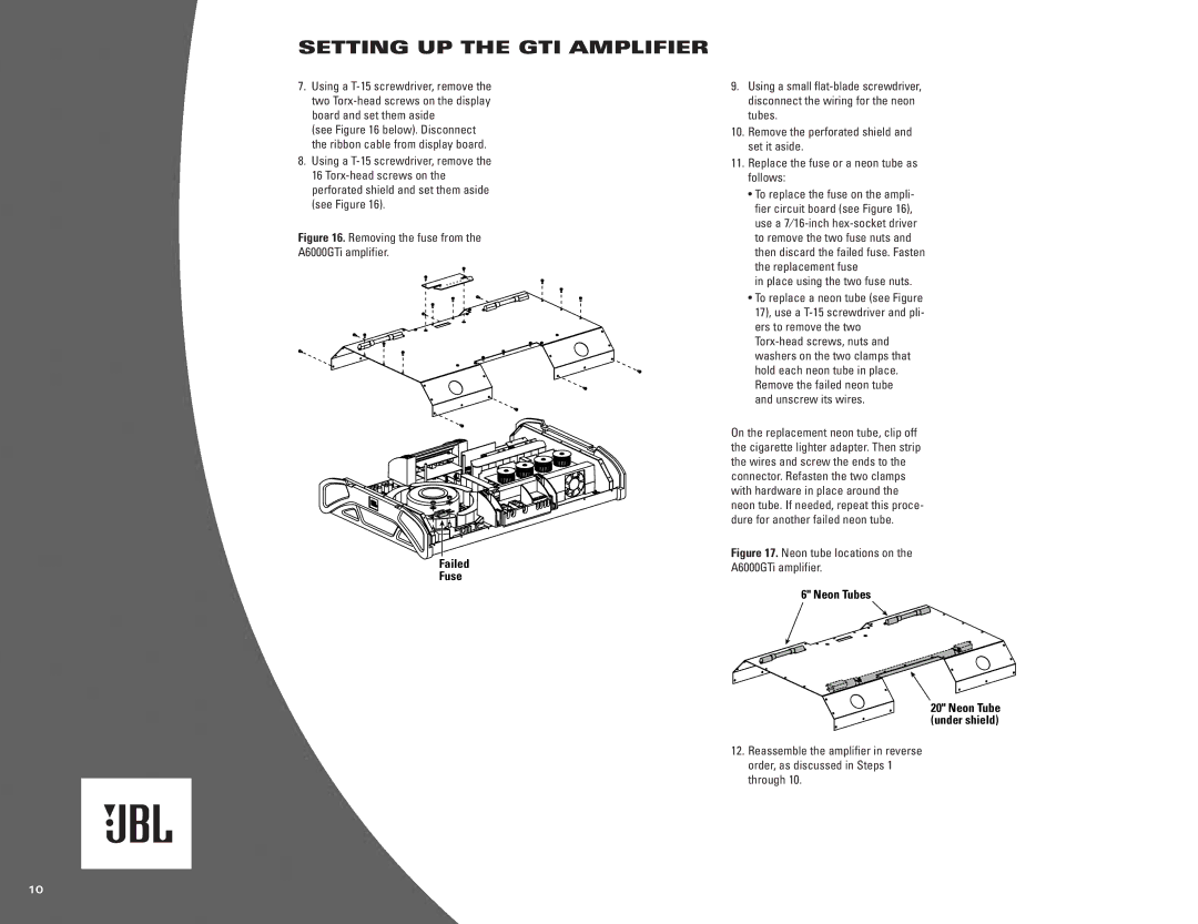
Figure 16. Removing the fuse from the
A6000GTi amplifier.
Failed
Fuse
9.Using a small
10.Remove the perforated shield and set it aside.
11.Replace the fuse or a neon tube as follows:
•To replace the fuse on the ampli- fier circuit board (see Figure 16), use a
in place using the two fuse nuts.
•To replace a neon tube (see Figure 17), use a
and unscrew its wires.
On the replacement neon tube, clip off the cigarette lighter adapter. Then strip the wires and screw the ends to the connector. Refasten the two clamps with hardware in place around the neon tube. If needed, repeat this proce- dure for another failed neon tube.
Figure 17. Neon tube locations on the
A6000GTi amplifier.
6" Neon Tubes
20" Neon Tube (under shield)
12.Reassemble the amplifier in reverse order, as discussed in Steps 1 through 10.
10