OPERATION AND CONTROLS
™
¡ |
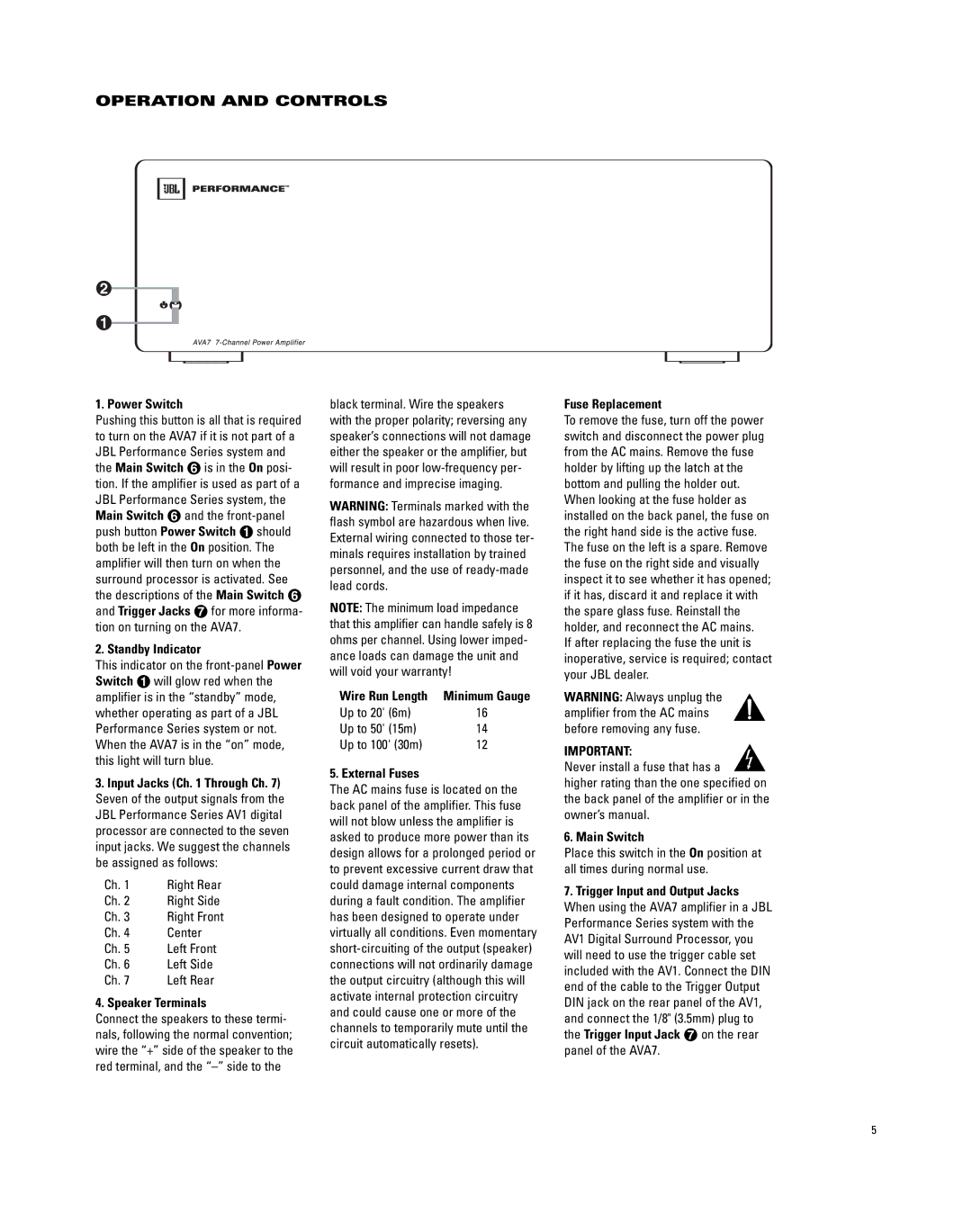
1. Power Switch
Pushing this button is all that is required to turn on the AVA7 if it is not part of a JBL Performance Series system and the Main Switch § is in the On posi- tion. If the amplifier is used as part of a JBL Performance Series system, the Main Switch § and the
2. Standby Indicator
This indicator on the
3.Input Jacks (Ch. 1 Through Ch. 7) Seven of the output signals from the JBL Performance Series AV1 digital processor are connected to the seven input jacks. We suggest the channels be assigned as follows:
Ch. 1 | Right Rear |
Ch. 2 | Right Side |
Ch. 3 | Right Front |
Ch. 4 | Center |
Ch. 5 | Left Front |
Ch. 6 | Left Side |
Ch. 7 | Left Rear |
4. Speaker Terminals
Connect the speakers to these termi- nals, following the normal convention; wire the “+” side of the speaker to the red terminal, and the
black terminal. Wire the speakers with the proper polarity; reversing any speaker’s connections will not damage either the speaker or the amplifier, but will result in poor
WARNING: Terminals marked with the flash symbol are hazardous when live. External wiring connected to those ter- minals requires installation by trained personnel, and the use of
NOTE: The minimum load impedance that this amplifier can handle safely is 8 ohms per channel. Using lower imped- ance loads can damage the unit and will void your warranty!
Wire Run Length | Minimum Gauge | |
Up to 20' | (6m) | 16 |
Up to 50' | (15m) | 14 |
Up to 100' (30m) | 12 | |
5. External Fuses
The AC mains fuse is located on the back panel of the amplifier. This fuse will not blow unless the amplifier is asked to produce more power than its design allows for a prolonged period or to prevent excessive current draw that could damage internal components during a fault condition. The amplifier has been designed to operate under virtually all conditions. Even momentary
Fuse Replacement
To remove the fuse, turn off the power switch and disconnect the power plug from the AC mains. Remove the fuse holder by lifting up the latch at the bottom and pulling the holder out. When looking at the fuse holder as installed on the back panel, the fuse on the right hand side is the active fuse. The fuse on the left is a spare. Remove the fuse on the right side and visually inspect it to see whether it has opened; if it has, discard it and replace it with the spare glass fuse. Reinstall the holder, and reconnect the AC mains.
If after replacing the fuse the unit is inoperative, service is required; contact your JBL dealer.
WARNING: Always unplug the amplifier from the AC mains before removing any fuse.
IMPORTANT:
Never install a fuse that has a
higher rating than the one specified on the back panel of the amplifier or in the owner’s manual.
6. Main Switch
Place this switch in the On position at all times during normal use.
7.Trigger Input and Output Jacks When using the AVA7 amplifier in a JBL Performance Series system with the AV1 Digital Surround Processor, you will need to use the trigger cable set included with the AV1. Connect the DIN end of the cable to the Trigger Output DIN jack on the rear panel of the AV1, and connect the 1/8" (3.5mm) plug to the Trigger Input Jack ¶ on the rear panel of the AVA7.
5