Manuals
/
JBL
/
Home Audio
/
Speaker
JBL
service manual
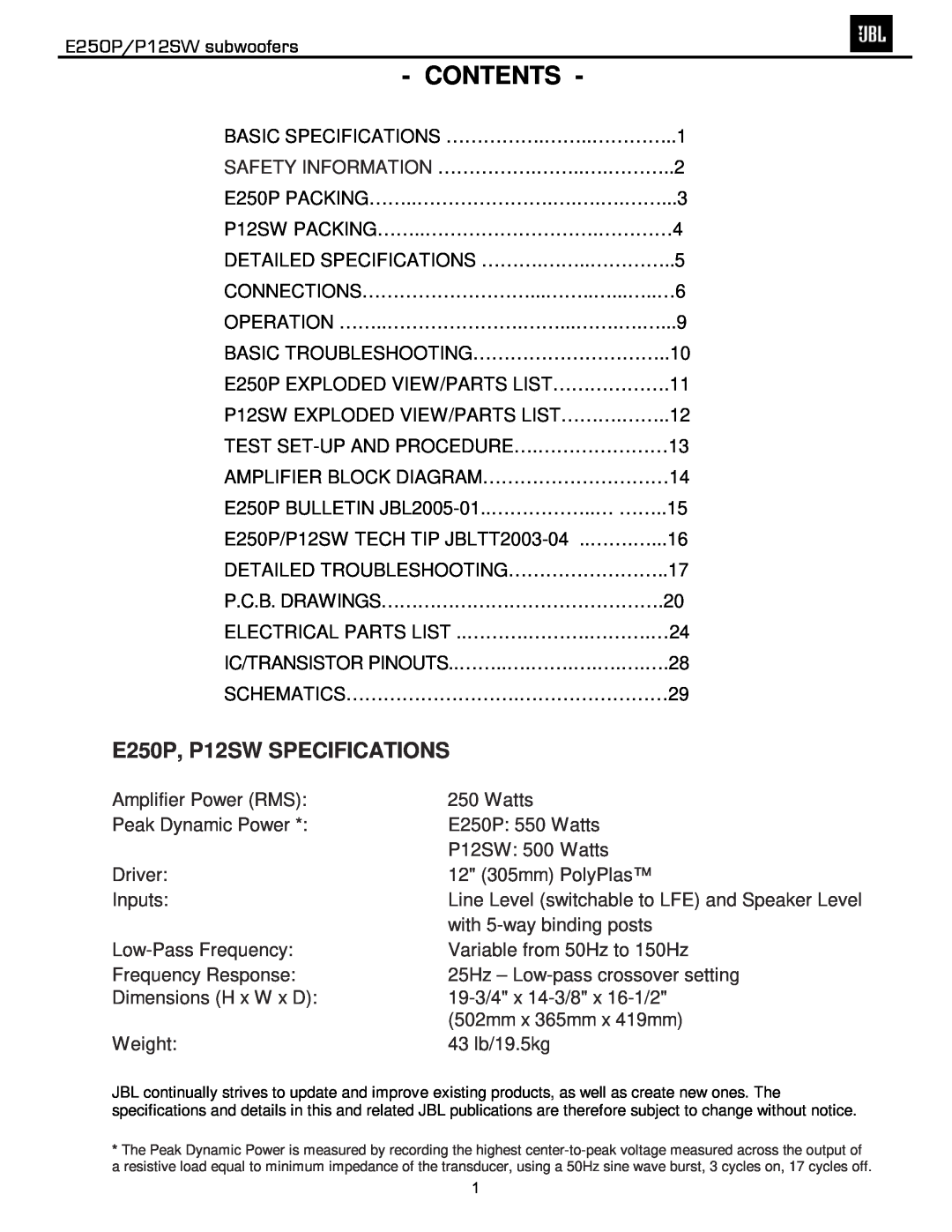
Contents, E250P/P12SW subwoofers, E250P, P12SW SPECIFICATIONS
Models:
P12SW
E250P
1
2
31
31
Download
31 pages
9.67 Kb
1
2
3
4
5
6
7
8
Troubleshooting
Specifications
Flow Chart
Test Set-Upand Procedure
Crossover Adjustments
Requiring Exact Replacements
Powered Subwoofers
Service Bulletin
Check Switching Frequency
Page 2
Image 2
Page 1
Page 3
Page 2
Image 2
Page 1
Page 3
Contents
Models
Powered Subwoofers
Northridge E-SeriesE250P Performance Series P12SW
250 Crossways Park Dr
E250P, P12SW SPECIFICATIONS
CONTENTS
E250P/P12SW subwoofers
Leakage/Resistance Check
List of Safety Components
Requiring Exact Replacements
Critical Components
E250P
Packaging
P12SW
Packaging
JBL E250P/P12SW Powered Sub/ Plate Amp
E250P/P12SW subwoofers
E250P/P12SW subwoofers
SPEAKER CONNECTION
Specification
QA Test
important that you avoid join
ing any other wires. Do not twist together
E250P/P12SW subwoofers
Subwoofer
Digital Receiver/Processor - LFE Connection
E250P/P12SW subwoofers
Analog Receiver/Processor - Line-LevelConnections
Crossover Adjustments
OPERATION
Power
E250P/P12SW subwoofers
E250P/P12SW subwoofers
TROUBLESHOOTING
Phase Control
E250P
Exploded View
P12SW
Exploded View
General Function UUT = Unit Under Test
TEST SET-UPAND PROCEDURE
E250P/P12SW subwoofers
Sweep Function
E250P/P12SW subwoofers
P10SW &P12SW
Service Bulletin
E250P subwoofer
P10SW, P12SW
For models E150P,E250P
TIP# JBLTT2003-04Rev2
PB10,PB12 Revision
2. Power Up LED RED
DETAILED TROUBLESHOOTING
A. Power Amp Section
4. Check Switching Frequency
2. High Level Input Sensitivity
DETAILED TROUBLESHOOTING CONTD
E250P/P12SW subwoofers
3. Low-Pass
E250P/P12SW subwoofers
DETAILED TROUBLESHOOTING CONTD
FLOW CHART
E250P/P12SW subwoofers
E250P/P12SW subwoofers
E250P/P12SW subwoofers
E250P/P12SW subwoofers
Resistors
E250P/P12SW 120v Electrical Parts List
E250P/P12SW subwoofers
Capacitors
E250P/P12SW subwoofers
Part Number
Semiconductors
Miscellaneous
E250P/P12SW subwoofers
Part Number
E250P/P12SW subwoofers
Part Number
Semiconductor Pinout Diagrams
E250P/P12SW subwoofers
P12SW Value of C65 = 47uf
See service bulletin for E250P
E250P/P12SW subwoofers
NOTE THIS VOLTAGE IS REFERENCED TO
NOT CIRCUIT GROUND
E250P/P12SW subwoofers
NOTE THIS VOLTAGE IS REFERENCED TO
Top
Page
Image
Contents