Installation Warnings and Tips
•Disconnect the negative (–) lead from your vehicle’s battery.
•At the installation sites, locate and make a note of all fuel lines, hydraulic brake lines, vacuum lines and electrical wiring. Use extreme caution when cutting or drilling in and around these areas.
•Choose a safe mounting location away from moisture.
•Make sure there is sufficient air circulation at the mounting location for the amplifier to cool itself.
•Mount the amplifier, using the supplied hardware.
Specifications
•40W RMS x 2 @ 4 ohms and ≤1% THD + N*
•60W RMS x 2 @ 2 ohms,
14.4V supply and ≤1% THD + N*
•120W RMS x 1 @ 4 ohms,
14.4V supply and ≤1% THD + N*
•Total peak power: 240 watts
•Frequency response: 10Hz – 100kHz
•Maximum input signal: 6V*
•Maximum sensitivity: 200mV*
•THD + N: 0.05%
•
•
*
0Speaker Output Connectors
•Connect the speakers to these terminals, observing proper polarity.
•
•
•Minimum speaker impedance for
1 Fuse
•Replace only with the same type and rating. 2 Power Input Connectors
•+12V: Connect to the positive terminal of the vehicle’s battery. 10 AWG wire is recommended. Install an appropriate fuse holder and fuse (15A minimum) within 18 inches of the battery. Make sure the wire is not damaged or pinched during installation. Install protective grommets when routing wires through the firewall or other sheet metal.
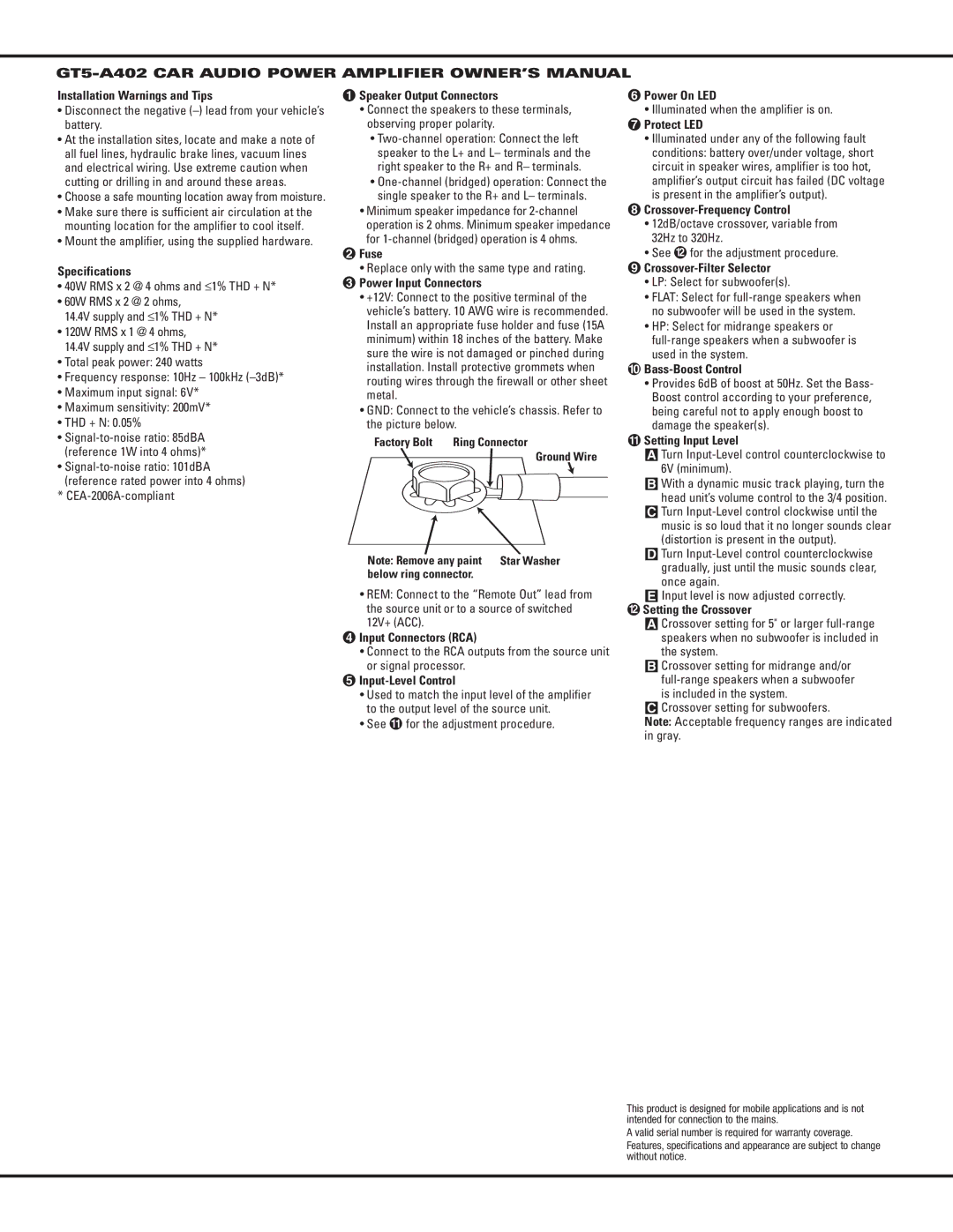
•GND: Connect to the vehicle’s chassis. Refer to the picture below.
Factory Bolt | Ring Connector |
Ground Wire
Note: Remove any paint Star Washer below ring connector.
•REM: Connect to the “Remote Out” lead from the source unit or to a source of switched 12V+ (ACC).
3Input Connectors (RCA)
•Connect to the RCA outputs from the source unit or signal processor.
4Input-Level Control
•Used to match the input level of the amplifier to the output level of the source unit.
•See A for the adjustment procedure.
5Power On LED
•Illuminated when the amplifier is on. 6 Protect LED
•Illuminated under any of the following fault conditions: battery over/under voltage, short circuit in speaker wires, amplifier is too hot, amplifier’s output circuit has failed (DC voltage is present in the amplifier’s output).
7Crossover-Frequency Control
•12dB/octave crossover, variable from 32Hz to 320Hz.
•See B for the adjustment procedure. 8
•LP: Select for subwoofer(s).
•FLAT: Select for
•HP: Select for midrange speakers or
9Bass-Boost Control
•Provides 6dB of boost at 50Hz. Set the Bass- Boost control according to your preference, being careful not to apply enough boost to damage the speaker(s).
ASetting Input Level
A Turn Input-Level control counterclockwise to 6V (minimum).
B With a dynamic music track playing, turn the head unit’s volume control to the 3/4 position.
C Turn
D Turn
E Input level is now adjusted correctly.
BSetting the Crossover
A Crossover setting for 5" or larger
B Crossover setting for midrange and/or
C Crossover setting for subwoofers.
Note: Acceptable frequency ranges are indicated in gray.
This product is designed for mobile applications and is not intended for connection to the mains.
A valid serial number is required for warranty coverage.
Features, specifications and appearance are subject to change without notice.