INPUT CONFIGURATIONS
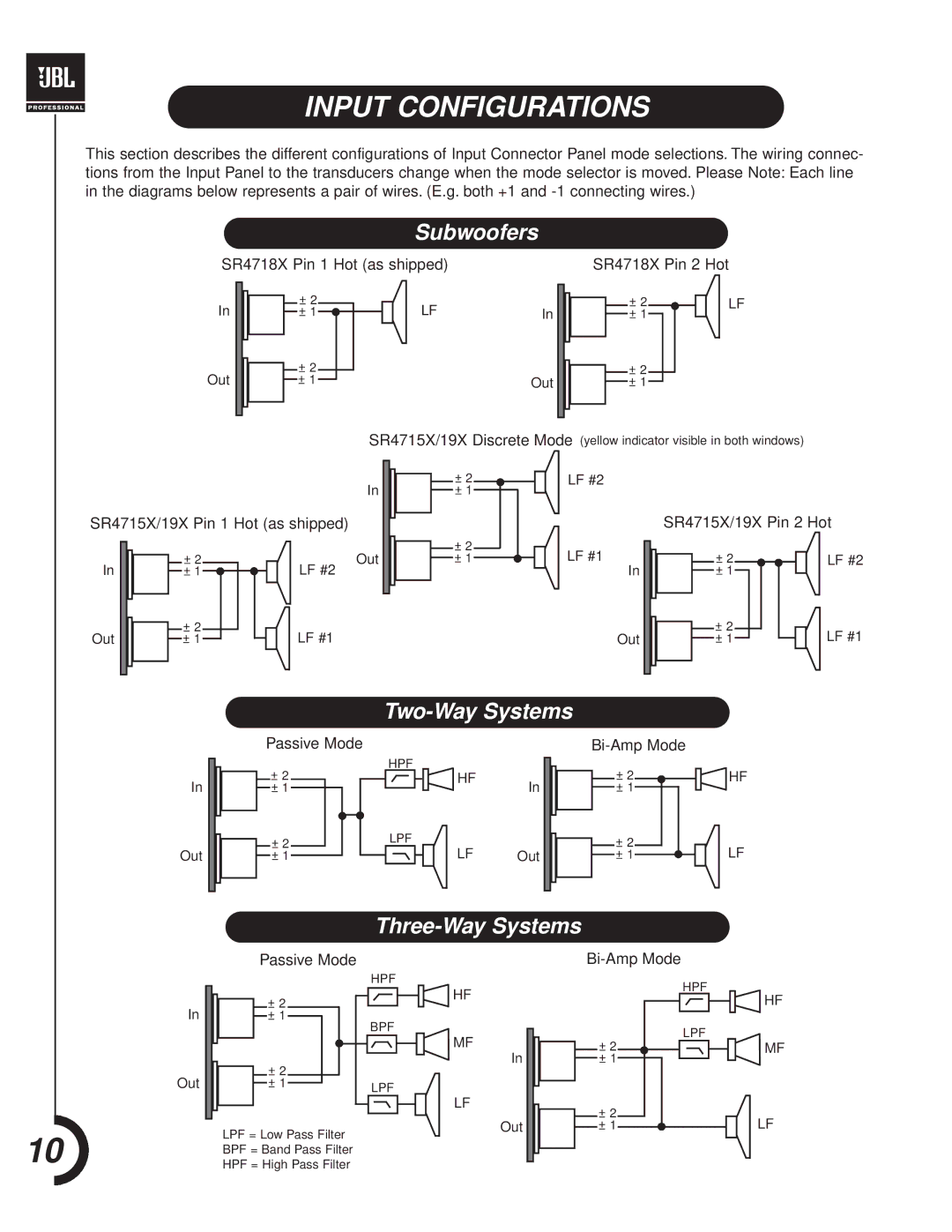
This section describes the different configurations of Input Connector Panel mode selections. The wiring connec- tions from the Input Panel to the transducers change when the mode selector is moved. Please Note: Each line in the diagrams below represents a pair of wires. (E.g. both +1 and
Subwoofers
SR4718X Pin 1 Hot (as shipped) | SR4718X Pin 2 Hot |
In
Out
±2
±1 ![]()
±2
±1
LFIn
Out
± 2
± 1
±2
±1
LF
SR4715X/19X Discrete Mode (yellow indicator visible in both windows)
In
SR4715X/19X Pin 1 Hot (as shipped)
In | ± 2 | Out |
± 1 | LF #2 |
±2
±1
±2
±1
LF #2
SR4715X/19X Pin 2 Hot
LF #1 | ± 2 | LF #2 |
In | ± 1 |
|
Out
±2
±1
LF #1 | Out |
±2
±1
LF #1
Two-Way Systems
In
Out
Passive Mode
HPF
± 2
± 1
± 2 |
|
|
|
| LPF |
± 1 |
|
|
|
|
|
|
|
|
|
|
HF
In
LF Out
± 2
± 1
± 2
± 1
HF
LF
Three-Way Systems
In
Out
10
Passive Mode
± 2
±1
±2
±1
LPF = Low Pass Filter
BPF = Band Pass Filter
HPF = High Pass Filter
HPF
BPF
LPF
HF
MF
In
LF
Out
HPF
LPF
± 2
± 1
± 2
± 1
HF
![]() MF
MF
LF