
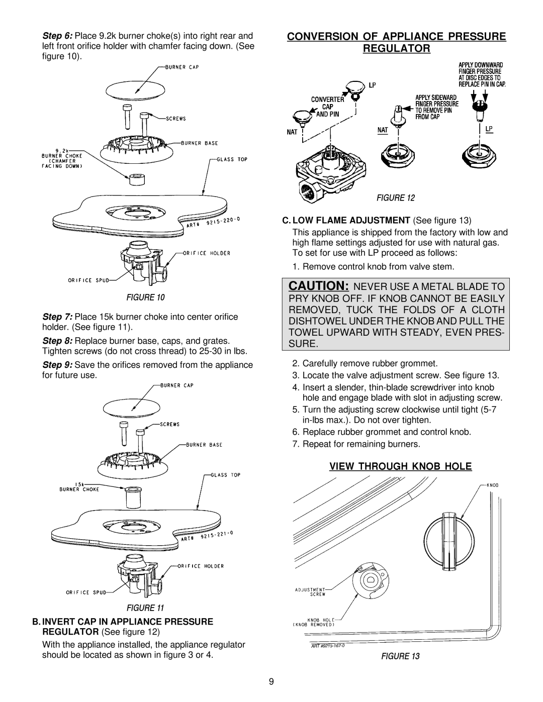
JGC9536, JGC9430 specifications
The Jenn-Air JGC9536 and JGC9430 are two prominent models in the realm of premium gas cooktops, designed to elevate culinary experiences in the modern kitchen. Both models offer a range of advanced features and technologies that cater to the needs of chefs at all skill levels.Starting with the JGC9536, this cooktop boasts a powerful 19,000 BTU burner, ideal for rapid boiling and high-heat searing. This feature is complemented by a versatile selection of burner sizes, including a 15,000 BTU dual-flame burner, which allows for precise temperature control. This burner is particularly advantageous for simmering sauces or slow-cooking delicate dishes. Additionally, the JGC9536 incorporates powerful 6,000 BTU burners that are excellent for everyday cooking tasks, providing a good balance between heat and efficiency.
The JGC9430, while slightly smaller, does not compromise on performance. It features a robust 16,000 BTU burner that provides ample power for a variety of cooking methods. Both models are equipped with continuous cast iron grates that allow for easy movement of pots and pans across the cooktop. This design not only enhances stability but also offers a professional look to the kitchen.
A notable technology integrated into both the JGC9536 and JGC9430 is the Precision Temperature Control. This feature provides consistent heat across the burners, ensuring food is cooked evenly. The high-performance ignition system is another highlight, allowing for quick and reliable burner lighting, which is essential for busy kitchen environments.
In terms of aesthetics, both models feature sleek stainless steel finishes and a sophisticated design that complements any kitchen décor. The illuminated knobs on the front provide not only a stylish touch but also practical visibility, making it easy to operate even in low-light conditions.
Safety features are also a focus for both cooktops. The flame-sensing technology automatically re-ignites the burner if the flame goes out, providing peace of mind while cooking. Additionally, the sealed burners minimize the risk of spills and allow for easy cleaning.
In summary, the Jenn-Air JGC9536 and JGC9430 gas cooktops are top-tier choices for those seeking to enhance their cooking experience. With powerful burners, advanced temperature control technologies, and a commitment to safety and aesthetics, these cooktops stand out as excellent investments for any kitchen. Whether for everyday cooking or culinary adventures, these models deliver exceptional performance and versatility.