INSTALLATION REQUIREMENTS
Tools and Parts
Gather the required tools and parts before starting installation. Read and follow the instructions provided with any tools listed here.
Tools needed
■ | Tape measure | ■ | Marker or pencil |
■ | ■ | Pliers | |
■ | Phillips head screwdriver | ■ | ¼" drill bit |
■ | Drill | ■ | Jigsaw |
■ | Level | ■ | Ratchet with ³⁄₈" socket |
■6" socket extension
Parts supplied
■Vent grille
■Grease filter
■Grill cartridge
■Grease container(s)
■
■Clamping screws (4)
Parts needed
■ A UL listed or CSA approved strain relief for ⁷⁄₈" (2.2 cm) |
knockout. |
■ A UL listed or CSA approved conduit connector for |
¹⁄₂" (1.3 cm) |
■ UL listed wire connectors |
■ Metal ducting |
■Use the countertop opening dimensions that are given with these Installation Instructions. Given dimensions are minimum clearances and provide 0" (0 cm) clearance.
■Grounded electrical supply is required. See “Electrical Requirements” section.
■If cabinet has drawers, drawers will need to be removed and drawer fronts installed on front of cabinet.
IMPORTANT: An
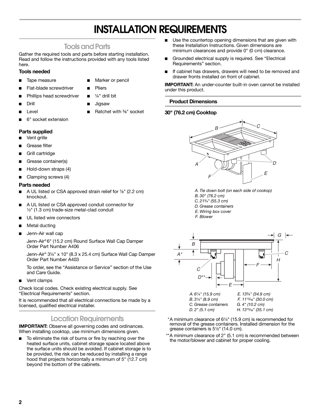
Product Dimensions
30" (76.2 cm) Cooktop
BC
A ![]()
![]() D
D
E
F
A. Tie down bolt (on each side of cookop)
B. 30" (76.2 cm)
C. 21³⁄₄" (55.3 cm)
D. Grease containers
E. Wiring box cover
F. Blower
■ |
Order Part Number A406 |
Order Part Number A403 |
To order, see the “Assistance or Service” section of the Use |
and Care Guide. |
■ Vent clamps |
Check local codes. Check existing electrical supply. See
B
A*
C
D** ![]()
E
F
G
![]()
![]() C H
C H
“Electrical Requirements” section.
It is recommended that all electrical connections be made by a licensed, qualified electrical installer.
Location Requirements
IMPORTANT: Observe all governing codes and ordinances. When installing cooktop, use minimum dimensions given.
■To eliminate the risk of burns or fire by reaching over the heated surface units, cabinet storage space located above the surface units should be avoided. If cabinet storage is to be provided, the risk can be reduced by installing a range hood that projects horizontally a minimum of 5" (12.7 cm) beyond the bottom of the cabinets.
A. 6¹⁄₄" (15.9 cm) | E. 13³⁄₄" (34.9 cm) |
B. 3¹⁄₂" (8.9 cm) | F. 11¹³⁄₁₆" (30.0 cm) |
C. Grease containers | G. 4" (10.2 cm) |
D. 2" (5.1 cm) | H. 13¹³⁄₁₆" (35.1 cm) |
*A minimum clearance of 6¹⁄₄" (15.9 cm) is recommended for removal of the grease containers. Installed dimension for the grease containers is 5¹⁄₂" (14.0 cm).
**A minimum clearance of 2" (5.1 cm) is recommended between the motor/blower and cabinet for proper cooling.
2