JCD2006
INSTALLATION |
| 7. | After completing the wiring connections, attach the front panel and turn the unit on to | |||||
Before You Begin |
|
| confirm operation (vehicle ignition switch must be on). If the unit does not operate, | |||||
|
| recheck all wiring until the problem is corrected. Once proper operation is achieved, turn | ||||||
1. | Disconnect Battery |
|
| the ignition switch off and proceed with final mounting of the chassis. | ||||
| Before you begin, always disconnect the battery negative terminal. | 8. | Carefully slide the radio into the mounting sleeve making sure it is | |||||
2. | Remove Transport Screws |
| 9. | fully seated and the spring clips lock it into place. | ||||
Important Notes |
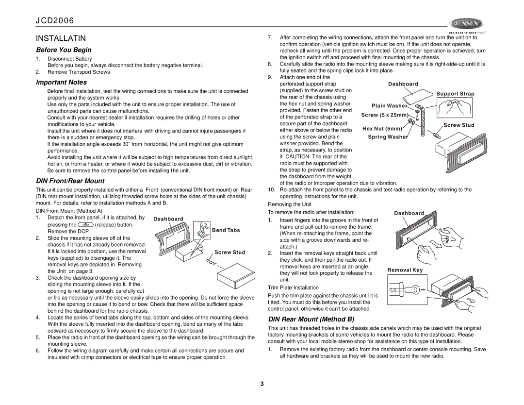
| Attach one end of the |
|
| ||||
|
| perforated support strap |
| Dashboard | ||||
• | Before final installation, test the wiring connections to make sure the unit is connected |
| (supplied) to the screw stud on |
| Support Strap | |||
| properly and the system works. |
|
| the rear of the chassis using |
| |||
|
|
|
|
| ||||
• | Use only the parts included with the unit to ensure proper installation. The use of |
| the hex nut and spring washer | Plain Washer | ||||
| unauthorized parts can cause malfunctions. |
|
| provided. Fasten the other end | Screw (5 x 25mm) | |||
• | Consult with your nearest dealer if installation requires the drilling of holes or other |
| of the perforated strap to a | |||||
|
|
| ||||||
| modifications to your vehicle. |
|
| secure part of the dashboard |
| Screw Stud | ||
• | Install the unit where it does not interfere with driving and cannot injure passengers if |
| either above or below the radio | Hex Nut (5mm) | ||||
|
|
| ||||||
| there is a sudden or emergency stop. |
|
| using the screw and plain | Spring Washer | |||
• | If the installation angle exceeds 30º from horizontal, the unit might not give optimum |
| washer provided. Bend the |
|
| |||
| performance. |
|
|
| strap, as necessary, to position |
|
| |
• | Avoid installing the unit where it will be subject to high temperatures from direct sunlight, |
| it. CAUTION: The rear of the |
|
| |||
| hot air, or from a heater, or where it would be subject to excessive dust, dirt or vibration. |
| radio must be supported with |
|
| |||
• | Be sure to remove the control panel before installing the unit. |
| the strap to prevent damage to |
|
| |||
DIN Front/Rear Mount |
|
| the dashboard from the weight |
|
| |||
|
| of the radio or improper operation due to vibration. | ||||||
This unit can be property installed with either a “Front” (conventional DIN front mount) or “Rear” | 10. | |||||||
(DIN rear mount installation, utilizing threaded screw holes at the sides of the unit chassis) |
| operating instructions for the unit. |
|
| ||||
mount. For details, refer to installation methods A and B. | Removing the Unit |
|
| |||||
DIN Front Mount (Method A) |
| To remove the radio after installation: |
| Dashboard | ||||
1. | Detach the front panel, if it is attached, by | Dashboard | 1. | Insert fingers into the groove in the front of |
| |||
| pressing the | (release) button. |
| |||||
|
|
| frame and pull out to remove the frame. |
| ||||
| Remove the DCP. |
| Bend Tabs |
|
| |||
|
|
| (When |
| ||||
2. | Slide the mounting sleeve off of the | 182 |
|
| ||||
|
| side with a groove downwards and re- |
| |||||
| chassis if it has not already been removed. |
|
|
| ||||
| 53 |
| attach.) |
|
| |||
| If it is locked into position, use the removal |
|
|
|
| |||
| Screw Stud | 2. | Insert the removal keys straight back until |
| ||||
| keys (supplied) to disengage it. The |
|
| they click, and then pull the radio out. If |
| |||
| removal keys are depicted in “Removing |
|
|
| ||||
|
|
| removal keys are inserted at an angle, |
| ||||
| the Unit” on page 3. |
|
|
| Removal Key | |||
|
|
|
| they will not lock properly to release the | ||||
3. | Check the dashboard opening size by |
|
|
| ||||
|
| unit. |
|
| ||||
| sliding the mounting sleeve into it. If the |
|
|
|
| |||
|
| Trim Plate Installation |
|
| ||||
| opening is not large enough, carefully cut |
|
|
| ||||
|
| Push the trim plate against the chassis until it is |
| |||||
| or file as necessary until the sleeve easily slides into the opening. Do not force the sleeve |
| ||||||
| fitted. You must do this before you install the |
| ||||||
| into the opening or cause it to bend or bow. Check that there will be sufficient space |
| ||||||
| behind the dashboard for the radio chassis. |
| control panel, otherwise it can't be attached. |
| ||||
4. | Locate the series of bend tabs along the top, bottom and sides of the mounting sleeve. | DIN Rear Mount (Method B) |
| |||||
| With the sleeve fully inserted into the dashboard opening, bend as many of the tabs | This unit has threaded holes in the chassis side panels which may be used with the original | ||||||
| outward as necessary to firmly secure the sleeve to the dashboard. | |||||||
| factory mounting brackets of some vehicles to mount the radio to the dashboard. Please | |||||||
5. | Place the radio in front of the dashboard opening so the wiring can be brought through the | |||||||
consult with your local mobile stereo shop for assistance on this type of installation. | ||||||||
| mounting sleeve. |
|
| |||||
|
|
| 1. | Remove the existing factory radio from the dashboard or center console mounting. Save | ||||
6. | Follow the wiring diagram carefully and make certain all connections are secure and | |||||||
| insulated with crimp connectors or electrical tape to ensure proper operation. |
| all hardware and brackets as they will be used to mount the new radio. | |||||
3