Guide Roller Adjustment
The bearings come
1.Disconnect machine from the power source.
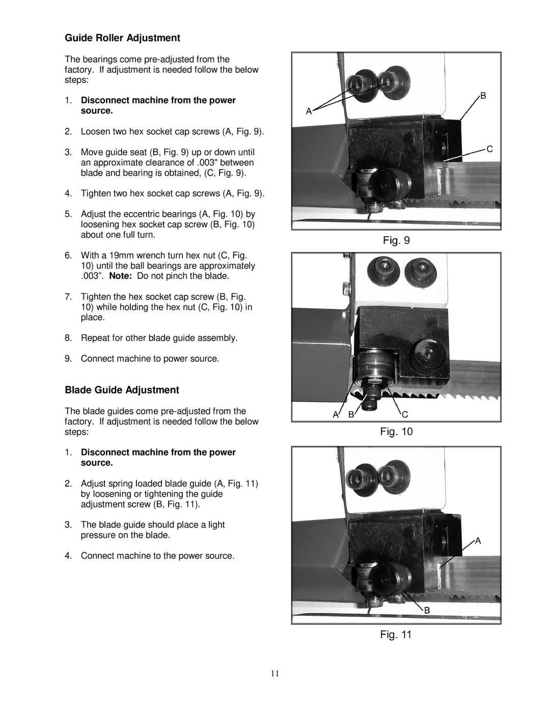
2.Loosen two hex socket cap screws (A, Fig. 9).
3.Move guide seat (B, Fig. 9) up or down until an approximate clearance of .003" between blade and bearing is obtained, (C, Fig. 9).
4.Tighten two hex socket cap screws (A, Fig. 9).
5.Adjust the eccentric bearings (A, Fig. 10) by loosening hex socket cap screw (B, Fig. 10) about one full turn.
6.With a 19mm wrench turn hex nut (C, Fig.
10)until the ball bearings are approximately
.003”. Note: Do not pinch the blade.
7.Tighten the hex socket cap screw (B, Fig.
10)while holding the hex nut (C, Fig. 10) in place.
8.Repeat for other blade guide assembly.
9.Connect machine to power source.
Blade Guide Adjustment
The blade guides come
1.Disconnect machine from the power source.
2.Adjust spring loaded blade guide (A, Fig. 11) by loosening or tightening the guide adjustment screw (B, Fig. 11).
3.The blade guide should place a light pressure on the blade.
4.Connect machine to the power source.
11