8
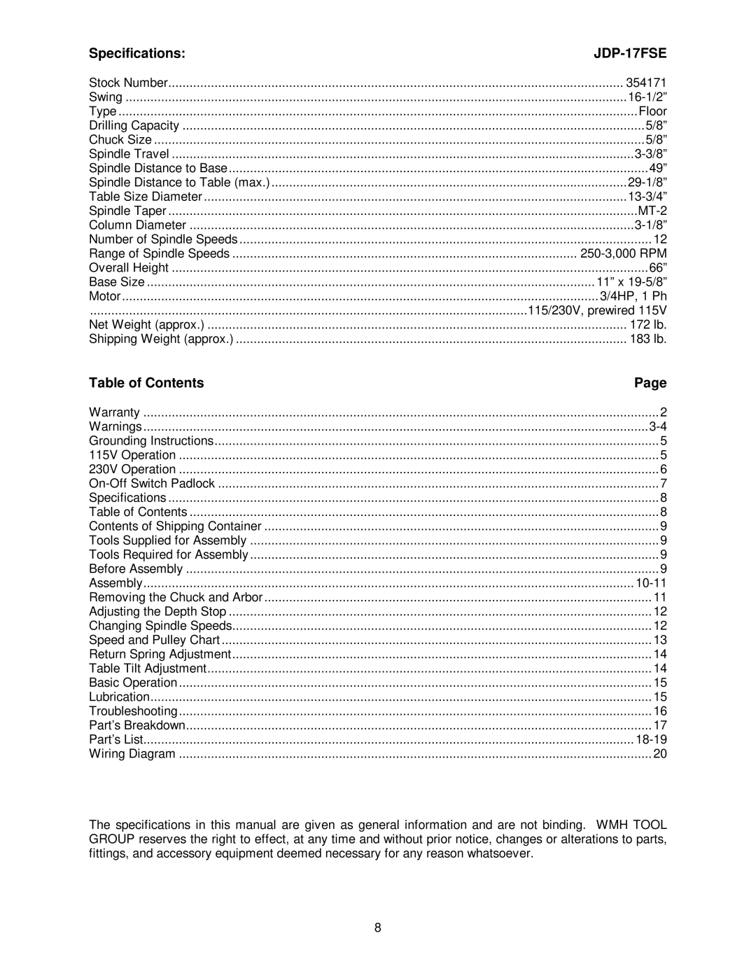
Specifications: JDP-17FSE
Stock Number................................................................................................................................354171
Swing.............................................................................................................................................16-1/2”
Type..................................................................................................................................................Floor
Drilling Capacity.................................................................................................................................. 5/8”
Chuck Size..........................................................................................................................................5/8”
Spindle Travel..................................................................................................................................3-3/8”
Spindle Distance to Base......................................................................................................................49”
Spindle Distance to Table (max.)....................................................................................................29-1/8”
Table Size Diameter.......................................................................................................................13-3/4”
Spindle Taper.................................................................................................................................... MT-2
Column Diameter.............................................................................................................................3-1/8”
Number of Spindle Speeds ....................................................................................................................12
Range of Spindle Speeds ................................................................................................. 250-3,000 RPM
Overall Height...................................................................................................................................... 66”
Base Size..............................................................................................................................11” x 19-5/8”
Motor......................................................................................................................................3/4HP, 1 Ph
...........................................................................................................................115/230V, prewired 115V
Net Weight (approx.) ...................................................................................................................... 172 lb.
Shipping Weight (approx.) .............................................................................................................. 183 lb.
Table of Contents Page
Warranty................................................................................................................................................. 2
Warnings..............................................................................................................................................3-4
Grounding Instructions............................................................................................................................. 5
115V Operation .......................................................................................................................................5
230V Operation .......................................................................................................................................6
On-Off Switch Padlock............................................................................................................................7
Specifications..........................................................................................................................................8
Table of Contents....................................................................................................................................8
Contents of Shipping Container............................................................................................................... 9
Tools Supplied for Assembly...................................................................................................................9
Tools Required for Assembly ...................................................................................................................9
Before Assembly.....................................................................................................................................9
Assembly..........................................................................................................................................10-11
Removing the Chuck and Arbor .............................................................................................................11
Adjusting the Depth Stop.......................................................................................................................12
Changing Spindle Speeds......................................................................................................................12
Speed and Pulley Chart......................................................................................................................... 13
Return Spring Adjustment......................................................................................................................14
Table Tilt Adjustment.............................................................................................................................14
Basic Operation.....................................................................................................................................15
Lubrication............................................................................................................................................. 15
Troubleshooting..................................................................................................................................... 16
Part’s Breakdown...................................................................................................................................17
Part’s List..........................................................................................................................................18-19
Wiring Diagram..................................................................................................................................... 20
The specifications in this manual are gi ven as general inform ation and are not binding. WMH TOOL
GROUP reserves the right t o ef f ect , at any t im e and wit hout pr ior noti ce, changes or al terat i ons to part s,
fittings, and accessory equipment deemed necessary f or any reason whatsoever.