9.The blade support bearing should be adjusted so that the back edge of the blade overlaps the front face of the ball bearing approximately 1/8". To change position of the bearing, remove screw (H, Fig. 19), and bearing (G, Fig. 19), and back off knurled knob (F, Fig. 19) completely to remove the bearing shaft. Notice the bearing holder on the shaft is eccentric.
Adjusting Lower Blade Guides and Blade Support Bearing
1.Disconnect machine from the power source.
2.Blade must already be tensioned and tracking properly.
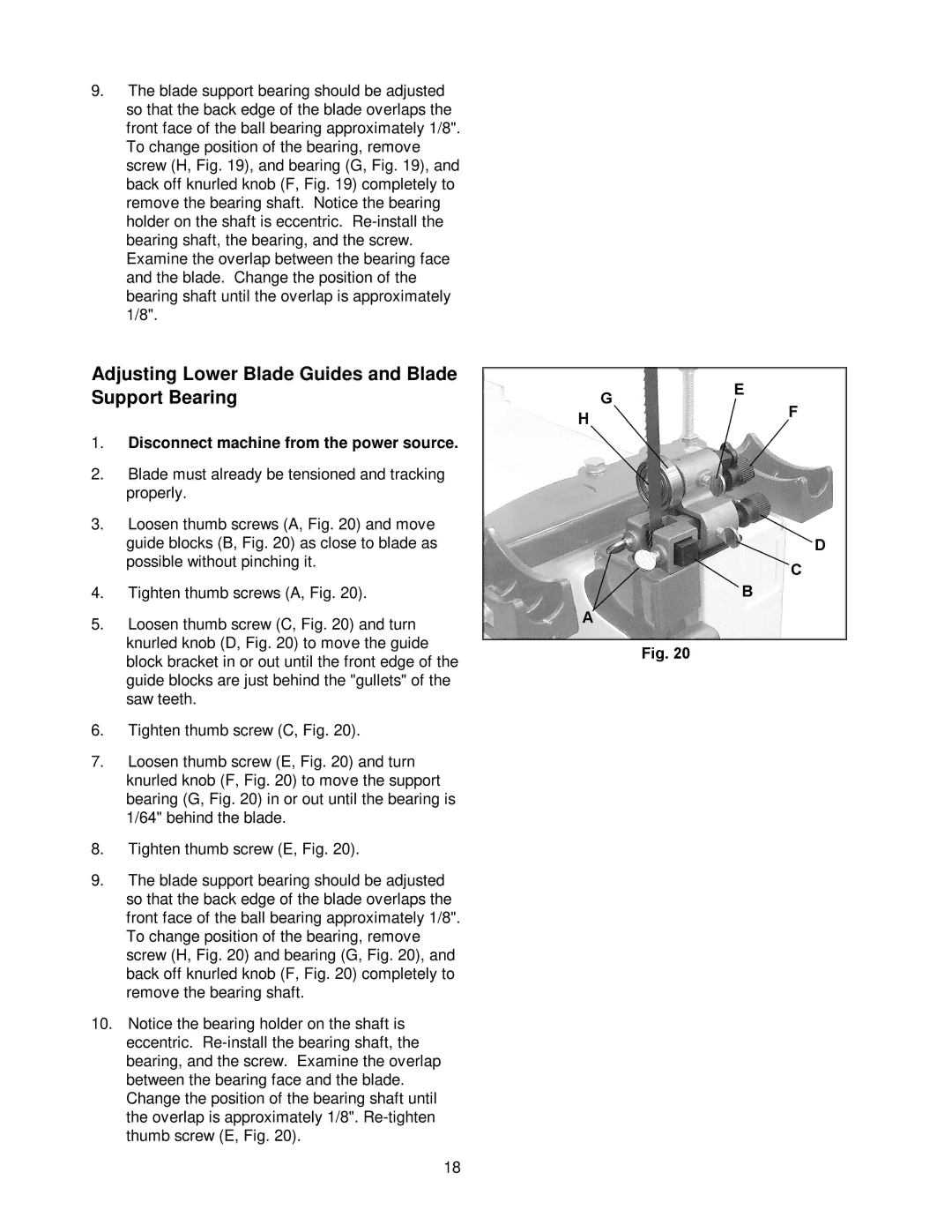
3.Loosen thumb screws (A, Fig. 20) and move guide blocks (B, Fig. 20) as close to blade as possible without pinching it.
4.Tighten thumb screws (A, Fig. 20).
5.Loosen thumb screw (C, Fig. 20) and turn knurled knob (D, Fig. 20) to move the guide block bracket in or out until the front edge of the guide blocks are just behind the "gullets" of the saw teeth.
6.Tighten thumb screw (C, Fig. 20).
7.Loosen thumb screw (E, Fig. 20) and turn knurled knob (F, Fig. 20) to move the support bearing (G, Fig. 20) in or out until the bearing is 1/64" behind the blade.
8.Tighten thumb screw (E, Fig. 20).
9.The blade support bearing should be adjusted so that the back edge of the blade overlaps the front face of the ball bearing approximately 1/8". To change position of the bearing, remove screw (H, Fig. 20) and bearing (G, Fig. 20), and back off knurled knob (F, Fig. 20) completely to remove the bearing shaft.
10.Notice the bearing holder on the shaft is eccentric.
18