Input Section
The XD600/6’s input section allows you to send signals to the amplifier section through the use of two, four or six
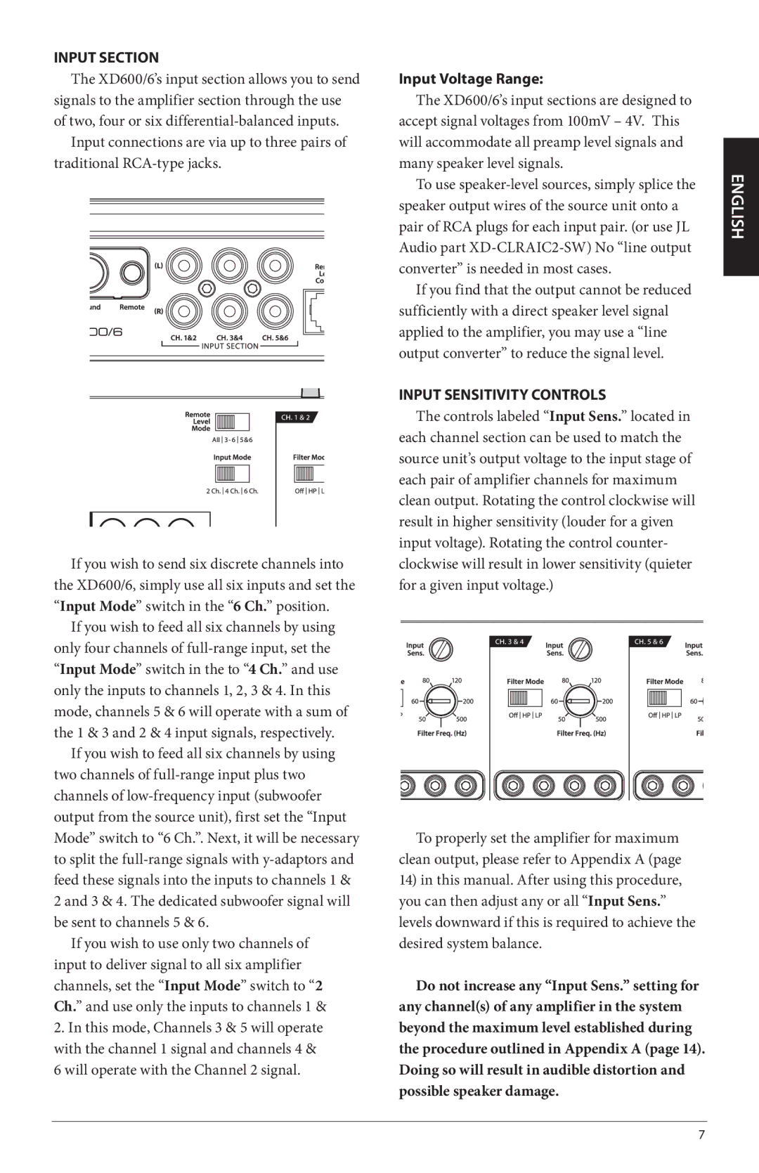
Input connections are via up to three pairs of traditional
If you wish to send six discrete channels into the XD600/6, simply use all six inputs and set the “Input Mode” switch in the “6 Ch.” position.
If you wish to feed all six channels by using only four channels of
If you wish to feed all six channels by using two channels of
If you wish to use only two channels of input to deliver signal to all six amplifier channels, set the “Input Mode” switch to “2 Ch.” and use only the inputs to channels 1 &
2.In this mode, Channels 3 & 5 will operate with the channel 1 signal and channels 4 &
6will operate with the Channel 2 signal.
Input Voltage Range:
The XD600/6’s input sections are designed to accept signal voltages from 100mV – 4V. This will accommodate all preamp level signals and many speaker level signals.
To use
If you find that the output cannot be reduced sufficiently with a direct speaker level signal applied to the amplifier, you may use a “line output converter” to reduce the signal level.
Input Sensitivity Controls
The controls labeled “Input Sens.” located in each channel section can be used to match the source unit’s output voltage to the input stage of each pair of amplifier channels for maximum clean output. Rotating the control clockwise will result in higher sensitivity (louder for a given input voltage). Rotating the control counter- clockwise will result in lower sensitivity (quieter for a given input voltage.)
To properly set the amplifier for maximum clean output, please refer to Appendix A (page
14)in this manual. After using this procedure, you can then adjust any or all “Input Sens.” levels downward if this is required to achieve the desired system balance.
Do not increase any “Input Sens.” setting for any channel(s) of any amplifier in the system beyond the maximum level established during the procedure outlined in Appendix A (page 14). Doing so will result in audible distortion and possible speaker damage.
ENGLISH
7