347337-UIM-A-0408

Connect the refrigerant lines using the following procedure:

1.Remove the cap and Schrader core from both the liquid and vapor service valve service ports at the outdoor unit. Connect low pres- sure nitrogen to the liquid line service port.

2.Braze the liquid line to the liquid valve at the outdoor unit. Be sure to wrap the valve body with a wet rag. Allow the nitrogen to con- tinue flowing.

3.Carefully remove the plugs from the evaporator liquid and vapor connections at the indoor coil.

FIGURE 5: Heat Protection

Do not install any coil in a furnace which is to be operated during the heating season without attaching the refrigerant lines to the coil. The coil is under 30 to 35 psig inert gas pressure which must be released to prevent excessive pressure build-up and possible coil damage.

4.Braze the liquid line to the evaporator liquid connection. Nitrogen should be flowing through the evaporator coil.

5.Slide the grommet away from the vapor connection at the indoor coil. Braze the vapor line to the evaporator vapor connection. After the connection has cooled, slide the grommet back into original position.

6.Protect the vapor valve with a wet rag and braze the vapor line connection to the outdoor unit. The nitrogen flow should be exiting the system from the vapor service port connection. After this con- nection has cooled, remove the nitrogen source from the liquid fit- ting service port.

7.Replace the Schrader core in the liquid and vapor valves.

8.Go to “SECTION V” or “SECTION IV” for orifice or TXV installation depending on application.

9.Leak test all refrigerant piping connections including the service port flare caps to be sure they are leak tight. DO NOT OVER- TIGHTEN (between 40 and 60 inch - lbs. maximum).

NOTE: Line set and indoor coil can be pressurized to 250 psig with dry nitrogen and leak tested with a bubble type leak detector. Then release the nitrogen charge.

NOTE: Do not use the system refrigerant in the outdoor unit to purge or leak test.

10.Evacuate the vapor line, evaporator, and liquid line to 500 microns or less.

11.Replace cap on service ports. Do not remove the flare caps from the service ports except when necessary for servicing the system.

Do not connect manifold gauges unless trouble is suspected. Approximately 3/4 ounce of refrigerant will be lost each time a stan- dard manifold gauge is connected.

12.Release the refrigerant charge into the system. Open both the liq- uid and vapor valves by removing the plunger cap and with an allen wrench back out counter-clockwise until valve stem just touches the chamfered retaining wall. See Page 3 "PRECAU-

TIONS DURING BRAZING SERVICE VALVE".

13.Replace plunger cap finger tight, then tighten an additional 1/12 turn (1/2 hex flat). Cap must be replaced to prevent leaks.

Never attempt to repair any brazed connections while the system is under pressure. Personal injury could result.

See "System Charge” section for checking and recording system charge.

Supplied with the outdoor unit is a Schrader Valve Core and Orifice for highest sales volume indoor coil. The valve core must be installed in equalizer fitting of the indoor coil.

SECTION IV: ORIFICE INSTALLATION

Failure to install Schrader Valve Core on orifice applications could result in total refrigerant loss of the system!

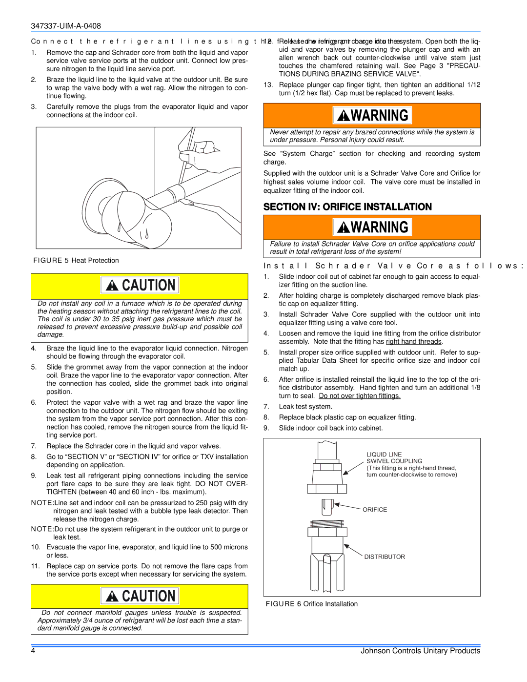
Install Schrader Valve Core as follows:

1.Slide indoor coil out of cabinet far enough to gain access to equal- izer fitting on the suction line.

2.After holding charge is completely discharged remove black plas- tic cap on equalizer fitting.

3.Install Schrader Valve Core supplied with the outdoor unit into equalizer fitting using a valve core tool.

4.Loosen and remove the liquid line fitting from the orifice distributor assembly. Note that the fitting has right hand threads.

5.Install proper size orifice supplied with outdoor unit. Refer to sup- plied Tabular Data Sheet for specific orifice size and indoor coil match up.

6.After orifice is installed reinstall the liquid line to the top of the ori- fice distributor assembly. Hand tighten and turn an additional 1/8 turn to seal. Do not over tighten fittings.

7.Leak test system.

8.Replace black plastic cap on equalizer fitting.

9.Slide indoor coil back into cabinet.

LIQUID LINE SWIVEL COUPLING

(This fitting is a right-hand thread, turn counter-clockwise to remove)

ORIFICE

DISTRIBUTOR

FIGURE 6: Orifice Installation

4

Johnson Controls Unitary Products

Page 4
Image 4
Johnson Controls 13 SEER installation manual Section IV Orifice Installation, Tions During Brazing Service Valve

13 SEER specifications

Johnson Controls has long been a leader in the HVAC industry, renowned for its commitment to energy efficiency and innovative technology. One of its prominent offerings is the 13 SEER air conditioning unit, which stands for Seasonal Energy Efficiency Ratio. This rating signifies a balance between initial cost and ongoing energy savings, making it an ideal choice for a range of residential and commercial applications.

The 13 SEER unit boasts several key features that set it apart from other air conditioning systems. Firstly, its robust design incorporates high-quality materials, ensuring durability and longevity. This unit is built to withstand various environmental conditions, making it a reliable option for any climate.

One of the standout technologies within the 13 SEER unit is its advanced scroll compressor. This component increases efficiency by minimizing energy consumption while maximizing cooling output. By operating quietly and smoothly, the scroll compressor contributes to a more comfortable indoor environment without the disruptive sounds often associated with traditional AC units.

Additionally, Johnson Controls has equipped the 13 SEER system with environmentally friendly refrigerants, aligning with modern standards for sustainability and reduced environmental impact. This eco-conscious approach ensures that the unit not only performs efficiently but also meets regulatory guidelines for emissions.

Ease of installation and maintenance is another significant advantage. The 13 SEER system is designed with user-friendliness in mind, allowing for straightforward setup, which can save on initial installation costs. Maintenance practices have also been simplified, with features such as easy access panels and diagnostic capabilities that help technicians identify and resolve issues quickly.

In terms of characteristics, the 13 SEER unit often comes equipped with a range of customizable options, including variable speed blower fans and smart connectivity features. These enhancements allow homeowners to optimize their cooling experience based on their individual preferences, promoting energy savings while ensuring comfort during the warmer months.

Overall, Johnson Controls' 13 SEER air conditioning unit provides an exceptional blend of efficiency, reliability, and innovative technology. With its eco-friendly refrigerants, advanced scroll compressor, and commitment to user-friendly design, this unit offers an optimal cooling solution for those seeking energy-efficient options in today’s environmentally conscious landscape. Whether for residential or commercial use, the 13 SEER air conditioning unit stands as a testament to Johnson Controls' dedication to excellence in the HVAC market.