
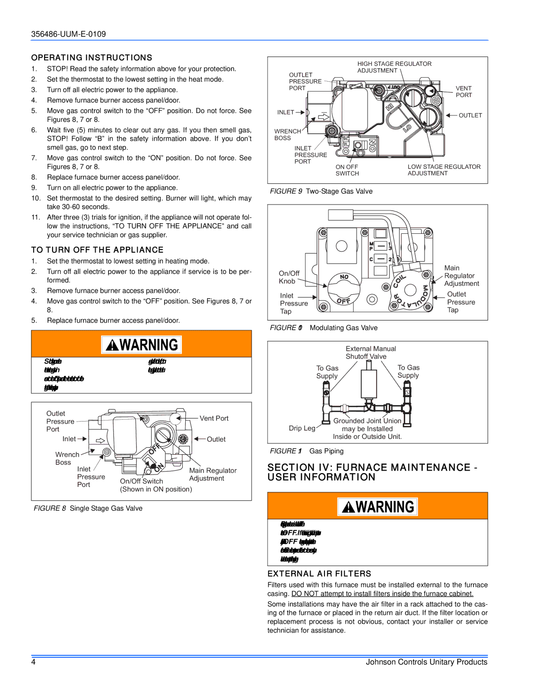
356486-UUM-E-0109 specifications
Johnson Controls is a reputed global leader in building technologies and solutions, and one of their innovative products is the Johnson Controls 356486-UUM-E-0109. This device is an advanced controller designed specifically for enhanced building management and energy efficiency.The 356486-UUM-E-0109 is engineered for seamless integration within existing building management systems, making it an ideal choice for new or retrofitted setups. One of its main features is its digital control capabilities, which allow for precise monitoring and management of various building systems such as HVAC, lighting, and security. Through its sophisticated algorithms, the controller optimizes energy consumption, ensuring that buildings run efficiently while reducing operational costs.
In terms of technology, the 356486-UUM-E-0109 utilizes state-of-the-art communication protocols, including BACnet and LonWorks. These protocols ensure interoperability with various devices from different manufacturers, which is crucial for modern smart buildings. The controller also supports both wired and wireless connectivity, providing flexibility in installation and communication.
Another key characteristic of the 356486-UUM-E-0109 is its intuitive user interface. It features a user-friendly touchscreen display that simplifies navigation and programming, allowing facility managers to easily monitor system operations. The device also provides real-time data analytics and reporting capabilities, empowering users to make informed decisions based on comprehensive insights into energy usage and system performance.
Furthermore, the 356486-UUM-E-0109 is designed with reliability and durability in mind. Built from high-quality materials, it is capable of withstanding various environmental conditions, making it suitable for diverse applications across different sectors, from commercial buildings to industrial facilities.
In summary, the Johnson Controls 356486-UUM-E-0109 is a powerful controller that enhances building management with its advanced digital capabilities, interoperability with other systems, and user-friendly interface. Its focus on energy efficiency, real-time data analytics, and robust construction makes it a valuable asset for any facility seeking to optimize operations and reduce costs.