Contents
Operator’s manual EPA
Symbols
KEY TO SYMBOLS
KEY TO SYMBOLS
CONTENTS
Contents
Note the following before starting
Dear customer
INTRODUCTION
What is what on the clearing saw? BC
WHAT IS WHAT?
What is what on the clearing saw? FC 2145, FC 2145 S, FC 2145 W
Decompression valve FC 2145 S, FC 2145 W
6 - English
What is what on the clearing saw? CC
WARNING! The ignition system of this
GENERAL SAFETY PRECAUTIONS
Personal protective equipment
WARNING! Listen out for warning signals or
Machine′s safety equipment
WARNING! Never use a machine with faulty
A BA B
Muffler
Cutting attachment guard
Vibration damping system
Quick release
WARNING! The inside of the muffler contain
Locking nut
Locking screw
WARNING! Mufflers fitted with catalytic
WARNING! Always stop the engine before
Cutting equipment
WARNING! Using an incorrect cutting
General rules
Trimmer head
Sharpening the saw blade
Assembling the handlebar and throttle BC 2145, CC
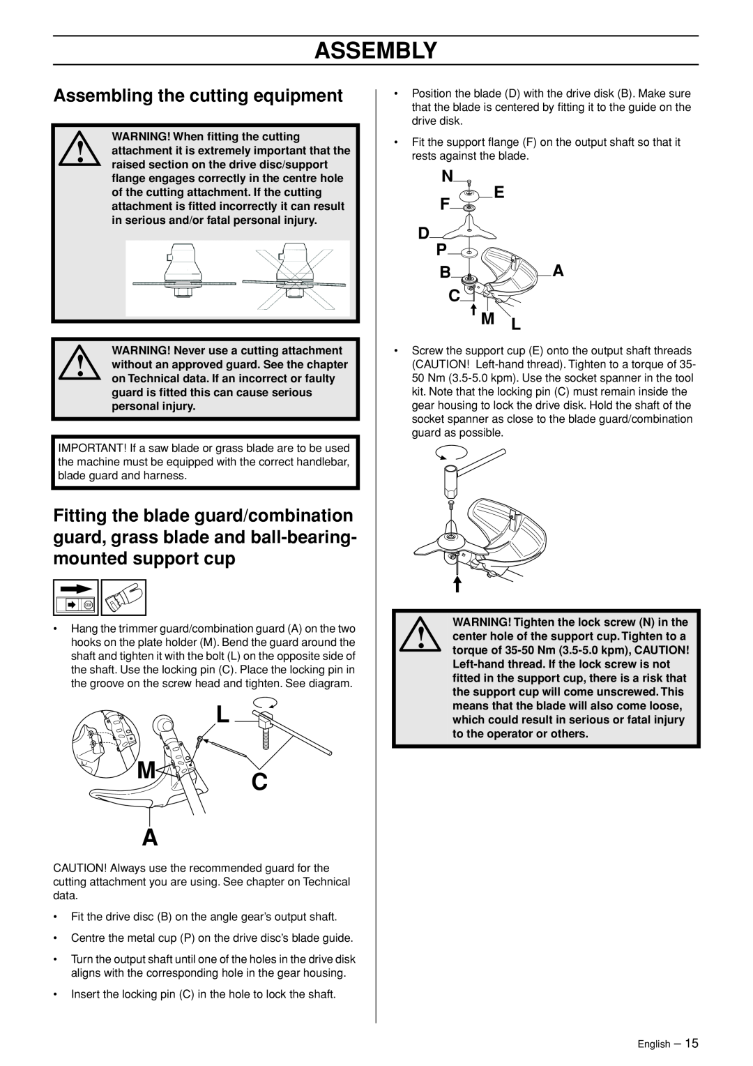
ASSEMBLY
Assembling the handlebar and throttle FC 2145, FC 2145 S, FC 2145 W
Transport position, handlebar
N E F P BA C
L M C A
Assembling the cutting equipment
WARNING! When fitting the cutting
H P B C
Fitting the blade guard and saw blade
Fitting the trimmer guard and trimmer head Trimmy SII
L M C A
WARNING! When using a clearing saw it
Adjusting the harness and clearing saw
Fitting other guards and cutting attachments
Standard harness
2 Grass clearing
Vector harness
WARNING! Take care when handling fuel
Fuel safety
FUEL HANDLING
Fuel
Do not smoke or place hot objects near fuel
Fueling
WARNING! Taking the following precautions will lessen the risk of fire
WARNING! The catalytic converter muffler
WARNING! The complete clutch cover and
STARTING AND STOPPING
Check before starting
Starting and stopping
Heated handles FC 2145 W
WARNING! When the engine is started with
Starting
Stopping
WORKING TECHNIQUES
General working instructions
WARNING! Neither the operator of the
WARNING! Machines fitted with saw blades
Working methods
WARNING! Watch out for thrown objects
WARNING! Sometimes branches or grass
Brush cutting with a saw blade
Grass clearing using a grass blade
Sweeping
Trimming
Clearing
Cutting
MAINTENANCE
Carburetor
WARNING! If the idle speed cannot be
Setting procedure without a load Blade can be used
Setting procedure with a load Trimmer head should be used
FC 2145, FC 2145 S, FC 2145 W Speed control at 13500 rpm
Proceed as follows
Muffler
Cooling system
Air filter
Cleaning the air filter
Bevel gear
Drive shaft
Spark plug
Temperature 5C 41F or colder
Winter use
Daily
Maintenance schedule
Maintenance
maintenance
FC 2145 S
TECHNICAL DATA
Technical data
Weight
Ignition system
FC 2145, FC 2145 S, FC 2145 W
Approved accessories
Type
Cutting attachment guard, Art. no
YOUR WARRANTY RIGHTS AND OBLIGATIONS
FEDERAL EMISSION CONTROL WARRANTY STATEMENT
Poly Trim
6 Nm
20mm
~ 3,5 m
Trimmy SII
095-.130
7,0 m
Page
2,7-3,3 mm
Auto
1,1 Kw
1,1 Kw
2,7-3,3 mm
Tap n’Go 45 Spin
10 m
10 cm 4,3 m
´z+Rvy¶5s¨ ´z+Rvy¶5s¨
Page
1150868-95 ´z+Rvy¶5s¨ ´z+Rvy¶5s¨