Manuals
/
Jonsered
/
Lawn and Garden
/
Chainsaw
Jonsered
GR 2126D
manual
Assembling the handlebars, Assembly of the blade and trimmer head
Models:
GR 2126D
1
17
32
32
Download
32 pages
8.37 Kb
14
15
16
17
18
19
20
21
Symbols
Maintenance
Assembly
Correctly adjusted carburettor
What is
Basic safety precautions
Safety
“Technical data“
Stop switch
Page 17
Image 17
Page 16
Page 18
Page 17
Image 17
Page 16
Page 18
Contents
Operator´s manual EPA
Symbols
SYMBOL EXPLANATION
List of contents
CONTENTS
The machine‘s safety equipment
SAFETY INSTRUCTIONS
Personal protective equipment
1. Throttle trigger lock
The stop switch should be used to stop the engine
2. Stop switch
3. Cutting attachment guard
4. Anti-vibration system
8. Locking nut
6. Muffler
7. Cutting equipment
Control, maintenance and service of the machine‘s safety equipment
Check that the guard is undamaged and not cracked
Reduce the machine‘s tendency to kickback
“Technical data“
Cutting equipment
Fuel safety
General safety instructions
Start
Transport and storage
Basic safety precautions
General working instructions
Designations
Basic clearing techniques
Adjusting the harness and clearing saw
Brush cutting using the saw blade
Grass clearing using a grass blade
Clearing‘s ABC
Working methods
Clearing
Grass clearing using the trimmer head and plastic blades
Trimming
Sweeping
What is what on the brushcutter?
WHAT IS WHAT?
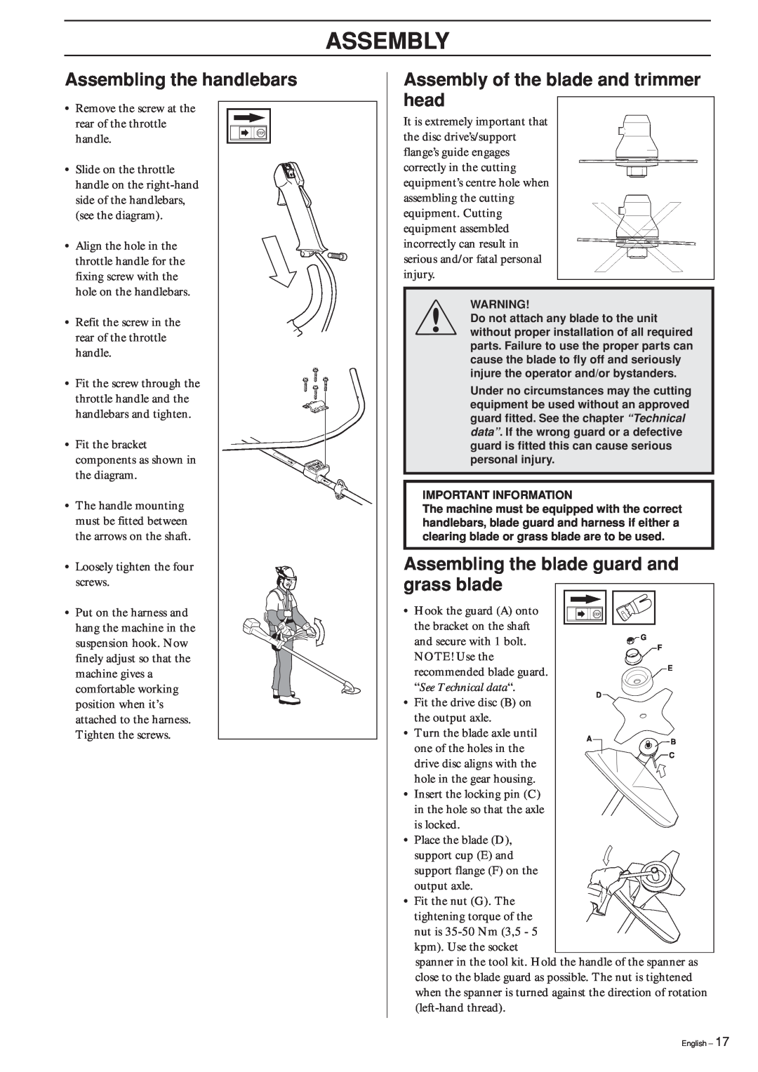
Assembly of the blade and trimmer head
ASSEMBLY
Assembling the handlebars
Assembling the blade guard and grass blade
Assembling the spray guard and trimmer head Tap´n´go Pro
Assembling the blade guard and clearing blade
Assembling other guards and cutting equipment
Adjusting the harness and clearing saw
Fuel mixture
FUEL HANDLING
Fuelling
This engine is certified to operate on unleaded gasoline
Start and stop
START AND STOP
Control before starting
Carburettor
MAINTENANCE
Recommended max. speed See “Technical Data”
Rec. idling speed 2700 rpm
High speed needle H
Final setting of the idling speed T
Correctly adjusted carburettor
Angle gear
Muffler
Cooling system
Spark plug
Air filter
Filing the grass blade
0,5 mm
Sharpening the clearing blade
Maintenance schedule
Daily maintenance
Weekly maintenance
GR2126D
TECHNICAL DATA
Technical data
YOUR WARRANTY RIGHTS AND OBLIGATIONS
EMISSION CONTROL WARRANTY STATEMENT
20mm
Poly Trim
6 Nm
´*xre¶5¶¨
Trimmy H
15 cm
30 - English
“Click”
Tap-N-Go Pro
2,0-2,4mm
080-.095
2002W11
´*xre¶5¶¨
108
Top
Page
Image
Contents