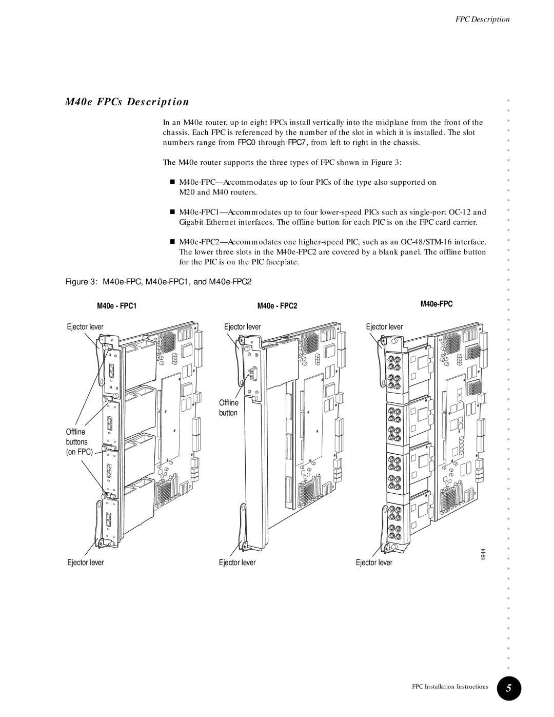
M40e, M40 specifications
Juniper Networks M40 and M40e are high-performance, modular routers designed to provide scalability, flexibility, and advanced capabilities for service providers and large enterprises. These platforms have made a significant impact in the networking industry due to their robust architecture and rich feature set.The Juniper M40 was introduced as a key player in the routing landscape, emphasizing performance and reliability. It is based on the innovative Junos operating system, which enables operators to manage network resources effectively. The M40 router features a flexible modular design, allowing for the installation of various interface cards that support multiple protocols and speeds. This versatility is crucial for adapting to evolving network demands.
One of the standout features of the M40 is its high throughput capability, supporting up to 40 Gbps with exceptional performance under heavy loads. This is complemented by advanced queuing and scheduling options that ensure efficient traffic management. The M40 also implements sophisticated routing protocols, such as BGP, OSPF, and MPLS, enabling service providers to enhance their network infrastructure with robust routing features.
The M40e variant enhances the original model with additional features and improved performance metrics. It is built for even greater scalability, supporting more interface types and higher capacities. The enhanced hardware of the M40e allows it to process data packets with lower latency, ensuring optimized performance for real-time applications such as voice and video.
Both M40 and M40e routers utilize a redundant architecture, providing high availability and fault tolerance. This is crucial for mission-critical applications where downtime can lead to significant operational disruptions and financial losses. The routers also boast advanced security features, including support for IPsec and various access control mechanisms, ensuring data integrity and confidentiality across the network.
In summary, the Juniper Networks M40 and M40e routers represent a significant evolution in networking technology. Their modular architecture, high throughput capabilities, advanced routing protocols, and robust security features make them ideal choices for service providers and enterprises looking to build resilient and high-performance networks. With their proven reliability and performance, these routers continue to serve as a foundation for modern networking solutions.

