f) LED Lights and Audible Alarm Safeties
The red LED indicates proper control voltage and will remain on unless a control voltage problem occurs. At startup a 5 second delay occurs while the board conducts an internal timer check. A short beep occurs when the power switch is turned OFF.
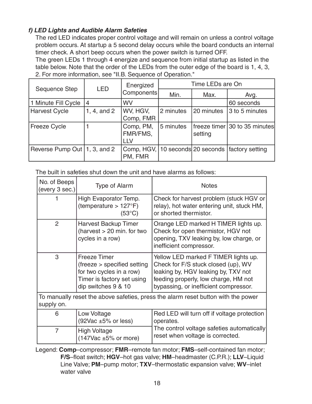
The green LEDs 1 through 4 energize and sequence from initial startup as listed in the table below. Note that the order of the LEDs from the outer edge of the board is 1, 4, 3, 2. For more information, see "II.B. Sequence of Operation."
Sequence Step | LED | Energized |
| Time LEDs are On | ||
Components | Min. | Max. | Avg. | |||
|
| |||||
|
|
| ||||
1 Minute Fill Cycle | 4 | WV |
|
| 60 seconds | |
Harvest Cycle | 1, 4, and 2 | WV, HGV, | 2 minutes | 20 minutes | 3 to 5 minutes | |
|
| Comp, FMR |
|
|
| |
Freeze Cycle | 1 | Comp, PM, | 5 minutes | freeze timer | 30 to 35 minutes | |
|
| FMR/FMS, |
| setting |
| |
|
| LLV |
|
|
| |
Reverse Pump Out | 1, 3, and 2 | Comp, HGV, | 10 seconds | 20 seconds | factory setting | |
|
| PM, FMR |
|
|
| |
|
|
|
|
|
| |
The built in safeties shut down the unit and have alarms as follows:
No. of Beeps | Type of Alarm | Notes | |
(every 3 sec.) | |||
|
| ||
|
|
| |
1 | High Evaporator Temp. | Check for harvest problem (stuck HGV or | |
| (temperature > 127°F) | relay), hot water entering unit, stuck HM, | |
| (53°C) | or shorted thermistor. | |
|
|
| |
2 | Harvest Backup Timer | Orange LED marked H TIMER lights up. | |
| (harvest > 20 min. for two | Check for open thermistor, HGV not | |
| cycles in a row) | opening, TXV leaking by, low charge, or | |
|
| inefficient compressor. | |
|
|
| |
3 | Freeze Timer | Yellow LED marked F TIMER lights up. | |
| (freeze > specified setting | Check for F/S stuck closed (up), WV | |
| for two cycles in a row) | leaking by, HGV leaking by, TXV not | |
| Timer is factory set using | feeding properly, low charge, HM not | |
| dip switches 9 & 10 | bypassing, or inefficient compressor. | |
|
|
|
To manually reset the above safeties, press the alarm reset button with the power supply on.
6 | Low Voltage | Red LED will turn off if voltage protection | |
| (92Vac ±5% or less) | operates. | |
|
| The control voltage safeties automatically | |
7 | High Voltage | ||
reset when voltage is corrected. | |||
| (147Vac ±5% or more) | ||
|
| ||
|
|
|
Legend:
18