1. Control Board Layout
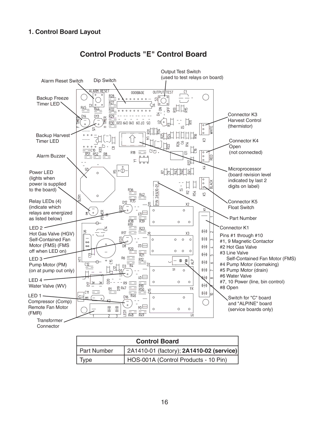
Control Products "E" Control Board
Alarm Reset Switch | Dip Switch |
Backup Freeze
Timer LED
Backup Harvest ![]()
![]()
![]()
![]()
![]()
Timer LED
Alarm Buzzer
Power LED (lights when power is supplied to the board)
Relay LEDs (4) (indicate which relays are energized as listed below)
LED 2
Hot Gas Valve (HGV)
Motor (FMS) (FMS off when LED on)
LED 3
Pump Motor (PM) (on at pump out only)
LED 4 ![]()
Water Valve (WV)
LED 1
Compressor (Comp) Remote Fan Motor (FMR)
Transformer
Connector
Output Test Switch
(used to test relays on board)
Connector K3 Harvest Control (thermistor)
Connector K4 Open
(not connected)
Microprocessor (board revision level indicated by last 2 digits on label)
Connector K5
Float Switch
Part Number
Connector K1
Pins #1 through #10
#1, 9 Magnetic Contactor #2 Hot Gas Valve
#3 Line Valve
#5 Pump Motor (drain) #6 Water Valve
#7, 10 Power (line, bin control) #8 Open
Switch for "C" board and "ALPINE" board (service boards only)
| Control Board |
|
|
Part Number | |
|
|
Type | |
|
|
16