14
Cycle Steps |
|
|
|
|
|
|
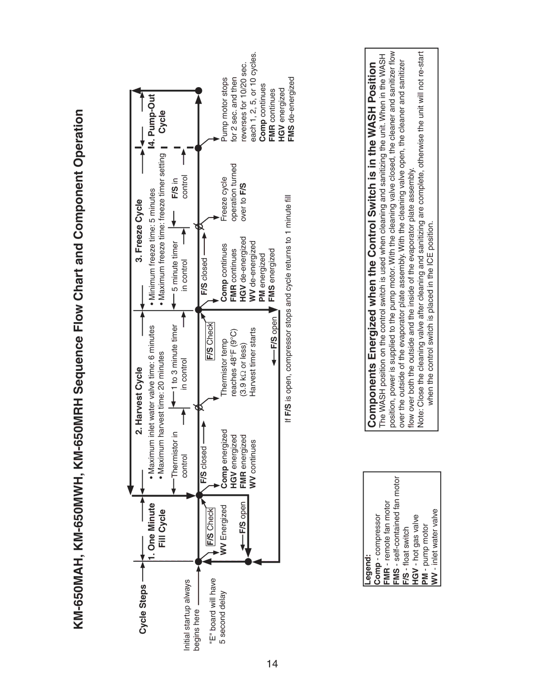
| 2. Harvest Cycle |
|
|
| 3. Freeze Cycle |
|
|
|
|
|
|
|
| 1. One Minute |
| • Maximum inlet water valve time: 6 minutes |
| • Minimum freeze time: 5 minutes | 4. | |||||||||||||
|
|
|
| ||||||||||||||||
|
|
| Fill Cycle |
| • Maximum harvest time: 20 minutes |
| • Maximum freeze time: freeze timer setting |
| Cycle | ||||||||||
|
| Thermistor in | 1 to 3 minute timer | 5 minute timer | F/S in |
|
Initial startup always |
| control | in control | in control | control |
|
|
|
|
|
|
| |
begins here |
| F/S closed |
| F/S closed |
|
|
"E" board will have | F/S Check | F/S Check |
|
| ||
|
|
|
| |||
|
|
|
|
|
| |
5 second delay | WV Energized | Comp energized | Thermistor temp | Comp continues | Freeze cycle | Pump motor stops |
| F/S open | HGV energized | reaches 48°F (9°C) | FMR continues | operation turned | for 2 sec. and then |
| FMR energized | (3.9 kΩ or less) | HGV | over to F/S | reverses for 10/20 sec. | |
|
| WV continues | Harvest timer starts | WV |
| each 1, 2, 5, or 10 cycles. |
|
|
|
| PM energized |
| Comp continues |
|
|
| F/S open | FMS energized |
| FMR continues |
|
|
| If F/S is open, compressor stops and cycle returns to 1 minute fill | HGV energized | ||
|
|
| FMS | |||
|
|
|
|
|
| |
Legend:
Comp - compressor FMR - remote fan motor FMS -
HGV - hot gas valve PM - pump motor WV - inlet water valve
Components Energized when the Control Switch is in the WASH Position
The WASH position on the control switch is used when cleaning and sanitizing the unit. When in the WASH position, power is supplied to the pump motor. With the cleaning valve closed, the cleaner and sanitizer flow over the outside of the evaporator plate assembly. With the cleaning valve open, the cleaner and sanitizer flow over both the outside and the inside of the evaporator plate assembly.
Note: Close the cleaning valve after cleaning and sanitizing are complete, otherwise the unit will not