11 |
Contents of STATUS SENSE |
When the STATUS SENSE (D7H) command is sent, the |
following data (5 bytes) is returned. |
Fourth byte |
| |
Bit No. | Status | When the bit is 1 |
7 | PLAY MODE | The VCR is playing back a tape. |
6 | FF MODE | The VCR is |
11
Contents of JVC STATUS SENSE
When the STATUS SENSE (DDH) command is sent, the following data (4 bytes) is returned.
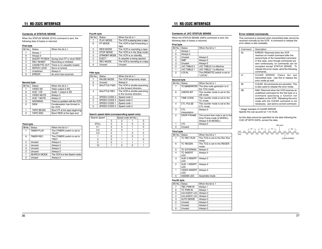
Error-related commands
This command is returned when transmitted data cannot be received normally by the VCR. A command to release the error status is also available.
First byte |
|
Bit No. Status | When the bit is 1 |
7Always 1
6Always 0
5 | SHORT FF/REW | During short FF or short REW |
4 | REC INHIBIT | Recording is inhibited. |
3 | CASSETTE OUT | There is no cassette loaded. |
2 | SERVO LOCK | Servo is locked. |
1 | Undefined | Always 0 |
0 | ERROR | An error has occurred. |
Second byte |
| |
Bit No. | Status | When the bit is 1 |
7 | VIDEO EE | Video output is EE. |
6 | AUD 1 EE | Audio 1 output is EE. |
5 | VIDEO MUTE | Always 0 |
4 | AUD 1 MUTE | Always 0 |
3 | WARNING | There is a problem with the VCR. |
2 | DEW | Condensation has formed in |
|
| the VCR. |
1 | TAPE BEGIN | Short FF at the tape beginning |
0 | TAPE END | Short REW at the tape end |
Third byte |
| |
Bit No. Status | When the bit is 1 | |
7 | TIMER PLAY | The [TIMER] switch is set to |
|
| “PLAY”. |
6 | TIMER REC | The [TIMER] switch is set to |
|
| “REC”. |
5 | Unused | Always 0 |
4 | Unused | Always 0 |
3 | Unused | Always 0 |
2 | Unused | Always 0 |
1 | SEARCH MODE | The VCR is in the Search mode |
0 | Unused | Always 0 |
|
|
| tape. |
|
|
5 | REW MODE | The VCR is rewinding a tape. | |||
4 | STOP MODE | The VCR is in the Stop mode. | |||
3 | STANDBY MODE | The VCR is on standby. |
| ||
2 | EJECT |
| A cassette is being ejected. | ||
1 | REC MODE | The VCR is recording on a tape | |||
0 | Unused |
| Unused |
|
|
Fifth byte |
|
|
|
| |
Bit No. | Status |
| When the bit is 1 |
| |
7 | PAUSE MODE | The VCR temporarily stops. | |||
6 | Unused |
| Always 0 |
|
|
5 | SHUTTLE FWD | The VCR is | |||
|
|
| in the forward direction. |
| |
4 | SHUTTLE REV | The VCR is | |||
|
|
| in the reverse direction. |
| |
3 | SPEED CODE 3 | Speed code 3 |
| ||
2 | SPEED CODE 2 | Speed code 2 |
| ||
1 | SPEED CODE 1 | Speed code 1 |
| ||
0 | SPEED CODE 0 | Speed code 0 |
| ||
Search speed table (corresponding speed only) |
| ||||
Search speed |
| Speed code (bit No.) |
| ||
|
| 3 | 2 | 1 | 0 |
STILL | 0 | 0 | 0 | 0 | |
0.1 | 0 | 0 | 1 | 0 | |
0.2 | 0 | 0 | 1 | 1 | |
0.3 | 0 | 1 | 0 | 0 | |
1 |
| 0 | 1 | 0 | 1 |
2 |
| 0 | 1 | 1 | 0 |
5 |
| 0 | 1 | 1 | 1 |
10 |
| 1 | 0 | 0 | 1 |
First byte
Bit No. Status
7Always 1
6Always 0
5 | Unused |
4 | DMF |
3 | Unused |
2JVC TABLE 2
1JVC TABLE 1
0LOCAL
Second byte
Bit No. Status
7TC GENERATOR
6USERS BIT
5TIME CODE
4CTL PULSE
3 | CTL |
| interpolation |
2 | DROP FRAME |
1 | LTC |
0 | Unused |
Third byte | |
Bit No. Status | |
7TC REC RUN
6TC REGEN
5TC EXTERNAL
4TC INSERT LED
3AUD 2 INSERT LED
2AUD 1 INSERT LED
1VIDEO INSERT LED
0ASSEM LED
Fourth byte | |
Bit No. Status | |
7 | TBC PWB IN |
6 | TC PWB IN |
5 | DA3 INSERT LED |
4 | DA4 INSERT LED |
3 | AUTO MODE |
2 | Unused |
1 | Unused |
0 | Unused |
When the bit is 1
Always 0 Always 0 Always 0 JVC TABLE 2 is effective. JVC TABLE 1 is effective. The [REMOTE] switch is set to “LOCAL”.
When the bit is 1 The time code generator is in the TCG mode. The counter mode is set to the UB mode. The counter mode is set to the TC mode. The counter mode is set to the CTL mode. Always 0
The current time code is set to the Drop Frame mode (U MODEL). Always 0 (E MODEL) Always 0
When the bit is 1 The TCG is set to the Rec Run mode. The TCG is set to the REGEN mode. Always 0 Always 0
Always 0
Always 0
Always 0
Assemble mode
When the bit is 1
Always 1
Always 1
Always 0
Always 0
Always 0
Always 0
Always 0
Always 0
Command Description
02ERROR: Returned when the VCR receives an invalid command after the second byte of the transmitted command. In this case, even though commands are sent continuously, no commands can be accepted except STATUS SENSE. To release this error mode, send the following commands.
41CLEAR ERROR: Clears the last transmitted byte. Use this to release the error mode as well.
56CLEAR: All commands are canceled. This is also used to release the error mode.
0B | NAK: Returned when the VCR receives an |
| undefined command for the first byte or a |
| command specifying a function not |
| available on the VCR. Releasing the error |
| mode with the CLEAR command is not |
| necessary. Just send a correct command. |
*Usage example of CLEAR ERROR Specify the
As this data cannot be specified for the data following the | |||||||||||||||||||||||||||
CUE UP WITH DATA, correct the data. |
|
|
|
|
|
|
|
|
|
| |||||||||||||||||
|
|
|
|
|
|
|
|
|
|
|
|
|
|
|
|
|
|
|
|
|
|
|
| ||||
TxD | B2 | 30 | 01 |
|
|
| 10 |
|
|
|
|
| 10 |
|
|
|
|
|
|
|
|
| 25 |
|
|
|
|
31 | 31 | 30 |
| 31 | 30 |
| 33 | 41 |
| 32 |
|
| 35 |
|
| ||||||||||||
|
| 0A | 0A | 0A | 0A | 0A | 0A | 0A |
|
|
|
|
|
|
|
| |||||||||||
RxD |
| 0A |
| 0A |
|
| 0A |
|
| 0A | |||||||||||||||||
|
|
|
|
|
|
|
|
|
|
|
|
|
|
|
|
|
|
|
|
|
|
|
|
|
|
| |
|
|
|
|
|
|
|
|
|
|
|
|
|
|
|
|
|
|
|
|
|
|
| |||||
|
|
|
|
|
|
|
|
|
|
|
|
|
|
|
|
|
| CLEAR ERROR |
|
|
| ||||||
36 | 37 |