GR-DVF25
It is recommended that you
Dear Customer
This unit is produced to comply with Standard IEC Publ
About Batteries
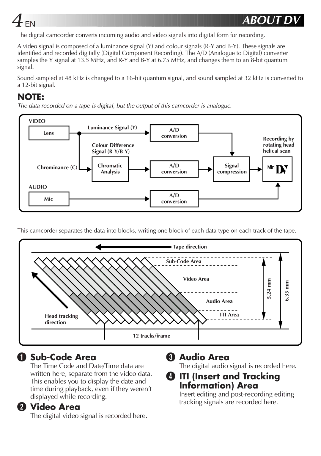
About DV
Contents
Charging the Battery Pack
Power
Using the Battery Pack
Using AC Power
Using a CAR Battery
Charge Marker
Choose which one means charged and which means discharged
Clock Lithium Battery Insertion/Removal
Insert Battery in Holder
Remove Battery Holder Pull out the battery holder
RE-INSERT Holder
Date/Time Settings
Select Operation Mode
Access DATE/TIME Menu
Access Recording Menu
Cont
Open LCD Monitor
Open Cassette Cover
INSERT/REMOVE Tape
Recording Mode Setting
SET Recording Mode
First move the highlight bar to REC Mode by
Set depending on your preference
Grip Adjustment
Viewfinder Adjustment
Adjust Length
Shoulder Strap Attachment
Tripod Mounting
Attach Strap
Power Switch Position
Full Auto mode
PRO. mode
Load a Cassette
Stop Recording
Press Display Button
Recording
Indicaitons reappear
Shooting While Watching The LCD Monitor
Recording Basic Recording
Before the following steps, perform pg
Interface Shooting
Journalistic Shooting
Brightness Control
Feature Picture Stabilizer
Basic Recording
Zoom
Zoom Out
Feature Video Light
To brighten the scene when natural lighting is too dim
When blank portion is recorded on a tape
Proper recording
Recording Advanced Features EN21
Displaying The Date And Time During Recording
Select Function
SET Function Parameters
Advanced Features
Snapshot Mode Selection
Snapshot
Snapshot Recording
Motor Drive Mode
EN23
Using Menu For Detailed Adjustment
Make Setting
END Setting
Select Function Parameters in DATE/TIME Menu or System Menu
Factory-preset
Recording Menu Explanations
Date/Time Menu Explanations
System Menu Explanations
Fade/Wipe Effects
Effect Selection
FADE/WIPE Selection
B K , , B W
Store Scene in Memory Engage the Record-Standby mode
Picture Wipe or Dissolve Selection P, P, P, P , P, P and P
Before the following steps, perform steps 1 through 3 on pg
If you select Picture Wipe/Dissolve during recording
Fader And Wipe Menu
Menu
Recording Advanced Features
Select Mode
Disable Mode
Programme AE With Special Effects
Shutter
Twilight
Sepia
Monotone
Auto Focus
Focusing
Patterns that are regularly repeated
Access Manual Mode Item Menu
Access Manual Focus
Adjust Focus
END Adjustment of Focus
Access Exposure Control
If you want to reset the exposure, repeat step
Exposure Control
To darken the image
Iris Lock
Centre SUBJECT, Lock Iris
Iris
To Return To Automatic Iris Control
White Balance Adjustment
Accessment White Balance Adjust
Select Auto in . Or set the Power Switch to
To Return To Automatic White Balance
Enter Setting
Manual White Balance Operation
Exit Manual White Balance AD- Justment
To Change The Tint For Recording
Playback Basic Playback
Speaker Volume Control
Rewind or Fast-forward the tape
Feature Still Playback
Feature Shuttle Search
Feature Slow-Motion Playback
Feature Playback Zoom
EN Playback
Playback Menu
Displaying The Time Code During Playback
Playback Sound
Recording sound Display Output sound
When connecting the cables, open this cover
EN Playback Connections
Use the provided Audio/Video A/V cable and S-Video cable
Use the provided Audio/Video A/V cable
Connectvcr Camcorder to TV or
Connectinput VCR Output to TV Supply Power
Turn on the camcorder, the VCR and the TV
Tape Dubbing
Pull OUT Battery Holder
Installing The Battery
Remote control uses one lithium battery CR2025
Functions
Buttons
To allow slow-speed search in either direction
To stop Slow-Motion Playback in progess, press Play
Playback Zoom
Activate Zoom
END Zoom
Down
Accessmenu Playback Effect Select
Playback Special Effects
Start Playback
Select Playback Effect
Random Assemble Editing R.A.Edit
SET REMOTE/VCR Code
SET Remote to Operate VCR
Operate VCR
Make Connections
Select Scenes
Select Scenes
USE FADE/WIPE on Scene Transition if Necessary
USE Programme AE with Special Effects if Necessary
Press FADE/WIPE
Prepare Source Tape
Automatic Editing to VCR
Stop Editing
For More Accurate Editing
Diagnosing VCR’S Against Camcorder Timing
Prepare for R.A. Edit
Choose a Scene
Adjustment of VCR’S Against Camcorder Timing
Access Playback Menu
Input Correction Data
Close Menu
Audio Dubbing
Begin Dubbing
Pause During Dubbing
Stop Dubbing
Original and new tracks are combined and output in stereo
New track is output on both L and R channels in stereo
Corrective Action
Snapshot mode cannot be used Digital Zoom does not work
Shutter mode of Programme
When using Picture Wipe
Delay of a fraction of a
Places subject to low Adjust the brightness
Camcorder When the LCD monitor’s Fluorescent light reaches
Picture Wipe function does not work
Disappear Than 1 second to make
Battery pack, etc., clock
Rear of the LCD monitor is hot
Images on the LCD monitor are jittery
LCD monitor or viewfinder indications blink
Power lamp blinks There are disturbances in audio
Temperature To protect the battery, it is
Recommended to charge it
Charging is difficult in places
Clean Exterior
Clean LCD Monitor
Clean Lens
After Use
64EN
Video Light Switch
$ Power Switch Battery Release Switch
Connectors to r are located beneath
External Stereo Microphone Input Connector MIC
Indications
LCD Monitor/Viewfinder Indications During Recording
Function
444
Indications Function
LCD Monitor/Viewfinder Indications During Playback
Function
Pg , 7
Pg , 42
Date/Time Display
Exposure Control ...................................... pg
For safety, do not
Avoid using the unit
To avoid hazard
During use
To prolong service life
Do not leave the unit
To protect the unit, do not
To prevent damage to the LCD monitor, do not
AC Power Adapter/Charger AA-V15EK
Connectors
Camcorder
General
GR-DVF25


 DV
DV