Preparation
Depending on your TV and other equipment there are various ways you can connect the player. Please refer to the manuals of your TV, VCR, stereo system or other devices as necessary for additional connection information.
Notes:
•The picture and sound of a nearby TV, VCR, or radio may be distorted during playback. Position the units away from each other or turn off the unit after removing the disc.
•Do not connect the unit’s AUDIO OUT jack to the phono in jack (record deck) of your audio system. Do not connect the unit via another VCR. The DVD image could be distorted by the copy protec- tion system.
Basic TV Connections
Make one of the following connections, depending on the capabilities of your TV.
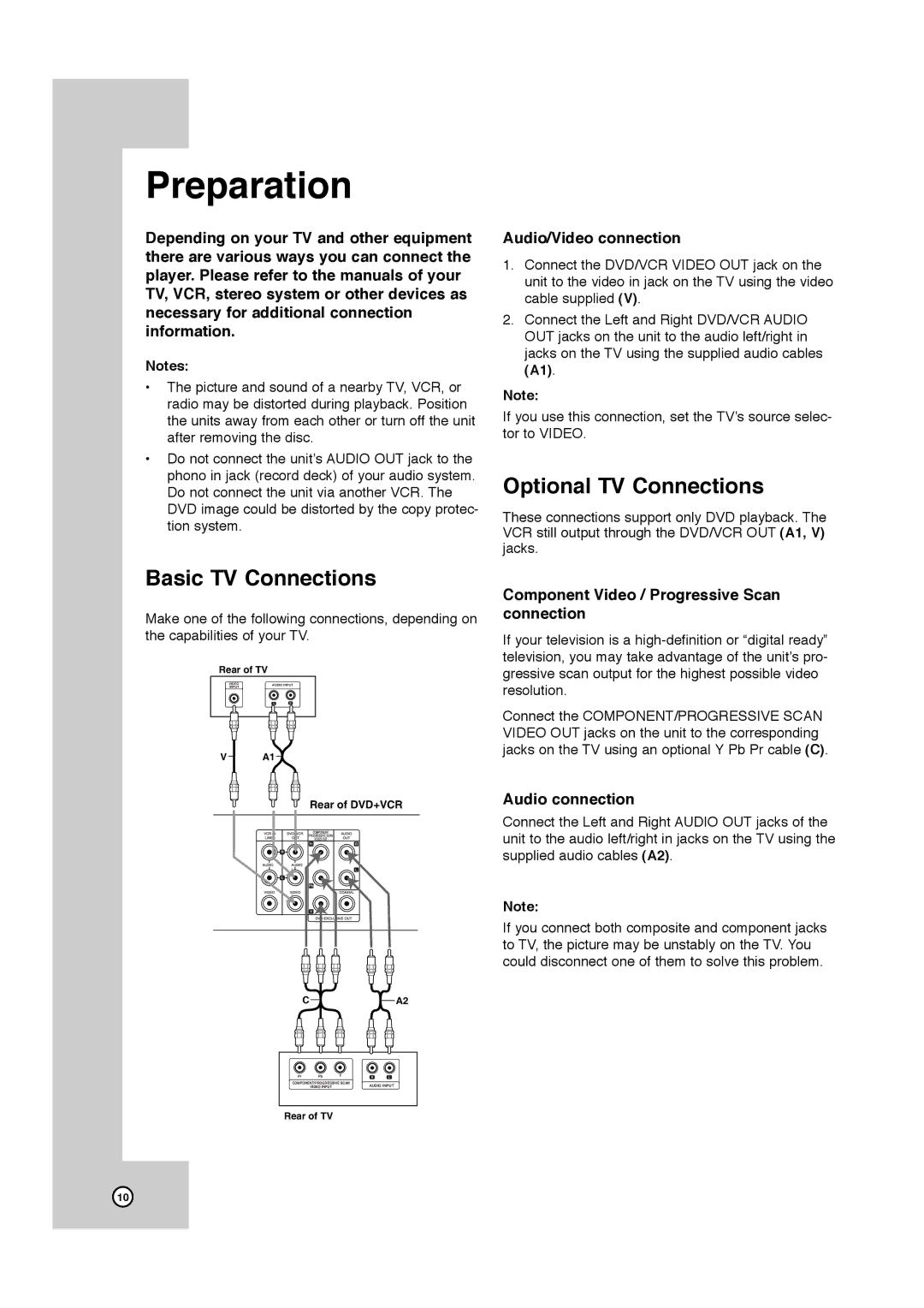
Rear of TV
VIDEO | AUDIO INPUT | |
INPUT |
|
|
| L | R |
V | A1 |
Rear of DVD+VCR
CA2
Pr | Pb | Y | R | L |
COMPONENT/PROGRESSIVE SCAN | AUDIO INPUT | |||
| VIDEO INPUT |
| ||
Rear of TV
Audio/Video connection
1.Connect the DVD/VCR VIDEO OUT jack on the unit to the video in jack on the TV using the video cable supplied (V).
2.Connect the Left and Right DVD/VCR AUDIO OUT jacks on the unit to the audio left/right in jacks on the TV using the supplied audio cables (A1).
Note:
If you use this connection, set the TV’s source selec- tor to VIDEO.
Optional TV Connections
These connections support only DVD playback. The VCR still output through the DVD/VCR OUT (A1, V) jacks.
Component Video / Progressive Scan connection
If your television is a
Connect the COMPONENT/PROGRESSIVE SCAN VIDEO OUT jacks on the unit to the corresponding jacks on the TV using an optional Y Pb Pr cable (C).
Audio connection
Connect the Left and Right AUDIO OUT jacks of the unit to the audio left/right in jacks on the TV using the supplied audio cables (A2).
Note:
If you connect both composite and component jacks to TV, the picture may be unstably on the TV. You could disconnect one of them to solve this problem.
10