ELECTRICAL CONNECTIONS

CONEXIONES ELECTRICAS

RACCORDEMENTS ELECTRIQUES

To prevent short circuits, we recommend that you disconnect the battery’s negative terminal and make all electrical connections before installing the unit.

Be sure to ground this unit to the car’s chassis again after installation.

Notes:

Replace the fuse with one of the specified rating. If the fuse blows frequently, consult your JVC car audio dealer.

It is recommended to connect to the speakers with maximum

power of more than 50 W (both at the rear and at the front, with an impedance of 4 to 8 ). If the maximum power is less than 50 W, change “AMP GAIN” setting to prevent the speakers from being damaged (see page 19 of the

INSTRUCTIONS).

To prevent short-circuit, cover the terminals of the UNUSED leads with insulating tape.

The heat sink becomes very hot after use. Be careful not to touch it when removing this unit.

Heat sink

Sumidero térmico

Dissipateur de chaleur

Para evitar cortocircuitos, recomendamos que desconecte el terminal negativo de la batería y que efectúe todas las conexiones eléctricas antes de instalar la unidad.

Asegúrese de volver a conectar a masa esta unidad al chasis del automóvil después de la instalación.

Notas:

Reemplace el fusible por uno con la corriente especificada. Si el fusible se quemase frecuentemente consulte con su concesionario de JVC de equipos de audio para automóviles.

Se recomienda conectar los altavoces con una potencia

máxima de más de 50 W (tanto atrás como adelante, con una impedancia de 4 a 8 ). Si la potencia máxima es de menos de 50 W, cambie “AMP GAIN” para evitar daños en los altavoces (consulte la página 19 del MANUAL DE INSTRUCCIONES).

Para evitar cortocircuitos, cubra los cables NO UTILIZADOS con cinta aislante.

El sumidero térmico estará muy caliente después del uso. Asegúrese de no tocarlo al desmontar esta unidad.

Pour éviter tout court-circuit, nous vous recommandons de débrancher la borne négative de la batterie et d’effectuer tous les raccordements électriques avant d’installer l’appareil.

Assurez-vous de raccorder de nouveau la mise à la masse de cet appareil au châssis de la voiture après l’installation.

Remarques:

Remplacer le fusible par un de la valeur précisée. Si le fusible saute souvent, consulter votre revendeur d’autoradios JVC.

Il est recommandé de connecter des enceintes avec une

puissance de plus de 50 W (les enceintes arrière et les enceintes avant, avec une impédance comprise entre 4 et

8 ). Si la puissance maximum est inférieure à 50 W, changez “AMP GAIN” pour éviter d’endommager vos enceintes (voir page 19 du MANUEL D’INSTRUCTIONS).

Pour éviter les court-circuits, couvrir les bornes des fils qui ne sont PAS UTILISÉS avec de la bande isolante.

Le dissipateur de chaleur devient très chaud après usage. Faire attention de ne pas le toucher en retirant cet appareil.

A Typical Connections / Conexiones tipicas / Raccordements typiques

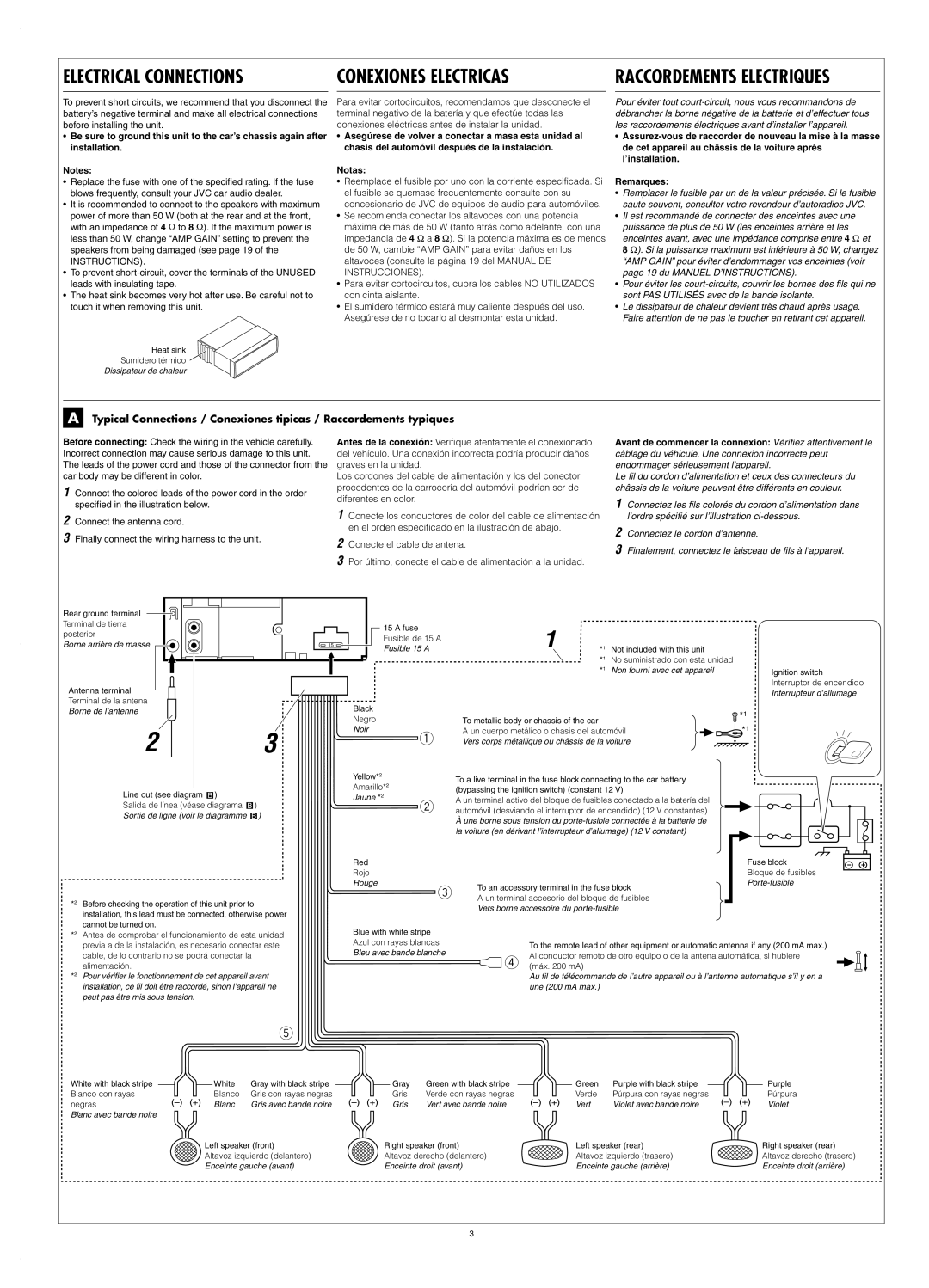
Before connecting: Check the wiring in the vehicle carefully. Incorrect connection may cause serious damage to this unit. The leads of the power cord and those of the connector from the car body may be different in color.

1Connect the colored leads of the power cord in the order specified in the illustration below.

2Connect the antenna cord.

3Finally connect the wiring harness to the unit.

Antes de la conexión: Verifique atentamente el conexionado del vehículo. Una conexión incorrecta podría producir daños graves en la unidad.

Los cordones del cable de alimentación y los del conector procedentes de la carrocería del automóvil podrían ser de diferentes en color.

1Conecte los conductores de color del cable de alimentación en el orden especificado en la ilustración de abajo.

2Conecte el cable de antena.

3Por último, conecte el cable de alimentación a la unidad.

Avant de commencer la connexion: Vérifiez attentivement le câblage du véhicule. Une connexion incorrecte peut endommager sérieusement l’appareil.

Le fil du cordon d’alimentation et ceux des connecteurs du châssis de la voiture peuvent être différents en couleur.

1Connectez les fils colorés du cordon d’alimentation dans l’ordre spécifié sur l’illustration ci-dessous.

2Connectez le cordon d’antenne.

3Finalement, connectez le faisceau de fils à l’appareil.

Rear ground terminal


Terminal de tierra


15 A fuse


1


posterior


Fusible de 15 A


Borne arrière de masse


15


*1

Not included with this unit


Fusible 15 A


*1

No suministrado con esta unidad


*1

Non fourni avec cet appareil


Ignition switch

Antenna terminal


Interruptor de encendido


Interrupteur d’allumage


Terminal de la antena


Black


Borne de l’antenne


*1


Negro


To metallic body or chassis of the car


2


3


Noir

A un cuerpo metálico o chasis del automóvil


*1


1

Vers corps métallique ou châssis de la voiture


Yellow*2

To a live terminal in the fuse block connecting to the car battery


Amarillo*2


Line out (see diagram


)


(bypassing the ignition switch) (constant 12 V)


Jaune *2

A un terminal activo del bloque de fusibles conectado a la batería del


Salida de línea (véase diagrama


)


2


automóvil (desviando el interruptor de encendido) (12 V constantes)


Sortie de ligne (voir le diagramme


)


À une borne sous tension du porte-fusible connectée à la batterie de


la voiture (en dérivant l’interrupteur d’allumage) (12 V constant)


Red


Fuse block


Rojo


Bloque de fusibles


Rouge

To an accessory terminal in the fuse block


Porte-fusible


3


*2

Before checking the operation of this unit prior to


A un terminal accesorio del bloque de fusibles


Vers borne accessoire du porte-fusible


installation, this lead must be connected, otherwise power


cannot be turned on.


Blue with white stripe


*2

Antes de comprobar el funcionamiento de esta unidad


previa a de la instalación, es necesario conectar este


Azul con rayas blancas


To the remote lead of other equipment or automatic antenna if any (200 mA max.)


Bleu avec bande blanche


cable, de lo contrario no se podrá conectar la


4

Al conductor remoto de otro equipo o de la antena automática, si hubiere


*2

alimentación.


(máx. 200 mA)


Pour vérifier le fonctionnement de cet appareil avant


Au fil de télécommande de l’autre appareil ou à l’antenne automatique s’il y en a


installation, ce fil doit être raccordé, sinon l’appareil ne


une (200 mA max.)


peut pas être mis sous tension.


5

White with black stripe


White

Gray with black stripe


Gray

Green with black stripe


Green

Purple with black stripe


Purple


Blanco con rayas


Blanco

Gris con rayas negras


Gris

Verde con rayas negras


Verde

Púrpura con rayas negras


Púrpura

negras


Blanc

Gris avec bande noire


Gris

Vert avec bande noire


Vert

Violet avec bande noire


Violet


Blanc avec bande noire


Left speaker (front)

Right speaker (front)

Left speaker (rear)

Right speaker (rear)

Altavoz izquierdo (delantero)

Altavoz derecho (delantero)

Altavoz izquierdo (trasero)

Altavoz derecho (trasero)

Enceinte gauche (avant)

Enceinte droit (avant)

Enceinte gauche (arrière)

Enceinte droit (arrière)

3

Page 27
Image 27
JVC KD-G210, KD-AR260 manual Electrical Connections

KD-G210, KD-AR260 specifications

The JVC KD-AR260 and KD-G210 are two popular car audio receivers that cater to different audio preferences and requirements. Both models present a blend of functionality, sound quality, and user-friendly features, making them great choices for enhancing in-car listening experiences.

Starting with the JVC KD-AR260, this model is designed to optimize audio playback in diverse conditions. One of its standout features is the 24-bit Digital-to-Analog Converter (DAC) that provides superior sound clarity. The receiver supports a wide range of media formats, including CDs, MP3, WMA, and USB playback. This versatility ensures that users can bring their favorite music along in various formats. Additionally, it boasts a built-in equalizer with customizable presets, giving users the ability to fine-tune their audio experience to suit their listening preferences.

Another noteworthy characteristic of the KD-AR260 is its compatibility with auxiliary inputs, letting users connect external devices such as smartphones and tablets easily. The vibrant, easy-to-read display enhances usability by providing clear visibility of track information and settings even in bright sunlight. The model also features a powerful amplification system that ensures rich sound quality, contributing to an impressive in-car audio experience.

Moving on to the JVC KD-G210, this model showcases an equally compelling set of features. With a strong emphasis on user convenience, the KD-G210 comes equipped with a front USB port for straightforward connectivity with devices. It supports playback for various file formats, including MP3, WMA, and AAC, catering to modern audio preferences.

The KD-G210 also incorporates an integrated Bluetooth system, allowing for hands-free calling and audio streaming directly from smartphones. This addition not only enhances safety by keeping drivers focused on the road but also adds an element of modern convenience to any drive. Moreover, it features a high-powered 50-watt output per channel, ensuring that users can enjoy robust sound without sacrificing audio clarity.

Both models possess an aesthetically pleasing design with customizable illumination options, allowing users to match the receiver's colors with their vehicle's interior. With their feature-rich designs, the JVC KD-AR260 and KD-G210 remain competitive options for anyone seeking enhanced audio performance in their car, blending technological advances with user-friendly applications. Overall, they stand as worthy contenders in today’s market, delivering quality sound and functionality for an enjoyable driving experience.