JVC KD-G305 manual “√µ√« Õ ª≠À“- ¢¥-¢ÈÕß, ‡¡ËÕµ‘¥µßÿ-È ¥ª√-Õ ‚¥¬‰¡Ë„Ȫ≈ÕÀÿÈ¡ /w, WOzUÐdNJ

Models: KD-G305

1 36
Download 36 pages 3.68 Kb
Page 34
Image 34
‡¡◊ËÕµ‘¥µß™ÿ—È ¥ª√–°Õ∫‚¥¬‰¡Ë„™Èª≈Õ°ÀÿÈ¡ /w

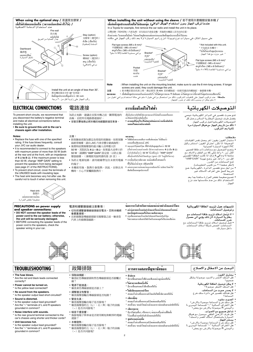
When using the optional stay /

/

‡¡◊ËÕ„™Èµ«¬÷— ¥·∫∫‡≈◊Õ°‰¥È(“¡“√∂‡≈◊Õ°‡ª‘¥§È“߉«È‰¥È) /


WO

Fire wall

Stay (option)

ºπß°—π‰ø—

When installing the unit without using the sleeve /

/

‡¡◊ËÕµ‘¥µß™ÿ—È ¥ª√–°Õ∫‚¥¬‰¡Ë„™Èª≈Õ°ÀÿÈ¡ /w


In a Toyota for example, first remove the car radio and install the unit in its place.

TOYOTA

µ«Õ¬Ë“߇™Ëπ— „π√∂¬πµÏ‚µ‚¬µÈ“ „ÀÈ∂Õ¥«‘∑¬ÿµ‘¥√∂¬πµÏÕÕ°°ËÕπ·≈–µ‘¥µß™ÿÈ— ¥ª√–°Õ∫π’ȇ¢È“‰ª·∑π


o¹d(« s

￿￿


µ«¬÷— ¥ (‡≈◊Õ°‰¥È)


G

©WO


H

Dashboard

I


·ºßÀπÈ“ª—∑¡Ï


Screw (option)

…—UO


°√Ÿ(‡≈◊Õ°‰¥È)


C

©w

Æt½UJ Ò

Flat type screws (M5 x 8 mm)*

EM5 x 8 mmF*

°√ŸÀ«‡√’¬∫— (M5 x 8 ¡‘≈≈‘‡¡µ√)*

*©rK∏ x M5® …bŽUIW¹u²wž«dÐ

Bracket*


￿￿*


·∑Ëπ√Õß√∫—*


*XO³¦²

Pocket


￿￿

Bracket*

°–‡ª“–

￿￿*

VOł

·∑Ëπ√Õß√∫—*


*XO³¦²

*Not included with this unit.

*‰¡Ë‰¥È„ÀÈ¡“°∫™ÿ— ¥ª√–°Õ∫π

Æ“UN'« «c¼ l ÒËe

*

Flat type screws (M5 x 8 mm)* EM5 x 8 mmF*

°√ŸÀ«‡√’¬∫— (M5 x 8 ¡‘≈≈‘‡¡µ√)*

*©rK x M5® …bŽUI

Install the unit at an angle of less than 30˚.

30°

µ‘¥µß™ÿÈ— ¥ª√–°Õ∫∑’Ë¡ÿ¡µË”°«Ë“ 30 Õß»“

ÆWł—œ ≥∞ s

Ò

Note

: When installing the unit on the mounting bracket, make sure to use the 8 mm-long screws. If longer


screws are used, they could damage the unit.

￿￿

:

=8 mm=

À¡“¬‡Àµ

: ‡¡◊ËÕµ‘¥µß™ÿ—È ¥ª√–°Õ∫≈ß„π·∑Ëπ√Õß√∫‰«È—„ÀÈ„™È°√Ÿ¬“«¢π“¥ 8 ¡‘≈≈‘‡¡µ√ ∂È“„™È°√Ÿ¬“«°«Ë“π’ÈÕ“®∑”„ÀÈ™ÿ¥ª√–°Õ∫‡ ’¬À“¬‰¥ô

s


∫WEŠö


Æ“UN−K

ELECTRICAL CONNECTIONS

°“√‡™◊ËÕ¡‚¥¬„™È‰øøÈ“

WOzUÐdNJ

To prevent short circuits, we recommend that


‡æ◊ËÕªÈÕß°π°“√‡°‘— ¥‰øøÈ“≈¥—«ß®√¢Õ·π–π”„ÀȪ≈¥¢«·∫µ‡µÕ√’Ë≈∫ÕÕ°È—

you disconnect the battery’s negative terminal


·≈È«®÷ßµËÕ

“¬‰ø°ËÕ𵑥µß‡§√◊ËÕßÈ—

and make all electrical connections before

µ√«®

Õ∫„ÀÈ·πË„®«Ë“‰¥È‡¥‘𠓬¥‘πµËÕ√–À«Ë“߇§√◊ËÕß°∫µ—«∂—ß—

installing the unit.

√∂¬πµÏ„À¡Ë·≈È«À≈ß®“°µ‘— ¥µßÈ—

Be sure to ground this unit to the car’s


chassis again after installation.


w

u½ ¨WOzUÐdNJ « dz«Ëb « w dOBIð ÀËbŠ lM*

q

qLŽË V U « W¹—UD³ « qO uð ·dÞ qBHÐ


Æ“UN'« VO dð q³

WOzUÐdNJ « öO

u² «

…d …—UO « qJO¼ l

“UN'« i¹—Qð s

b Qð


ÆVO d² « bFÐ WO½UŁ

Notes:

Replace the fuse with one of the specified rating. If the fuse blows frequently, consult your JVC car audio dealer.

It is recommended to connect to the speakers with maximum power of more than 50 W (both

at the rear and at the front, with an impedance of 4 to 8 ). If the maximum power is less than 50 W, change “AMP GAIN” setting to prevent the speakers from being damaged (see page 21 of the INSTRUCTIONS).

To prevent short-circuit, cover the terminals of the UNUSED leads with insulating tape.

The heat sink becomes very hot after use. Be careful not to touch it when removing this unit.


À¡“¬‡Àµÿ:


„™Èæ‘°¥—®”‡æ“–·∑πø‘« À“°ø‘« ¢Ï“¥∫ËÕ¬ „ÀȪ√÷°…“√È“


JVC


π¢“¬‡§√◊ËÕ߇ ¬ß√∂¬πµÏ’JVC


¢Õ·π–π”„ÀȵËÕ≈”‚æß ∑’Ë¡’°”≈ß—¢—∫ Ÿß ÿ¥‡°‘π°«Ë“ 50 W

50 W

4 – 8


(∑—ÈߥȓπÀπÈ“·≈–¥È“πÀ≈—ß ¡’§Ë“§«“¡µÈ“π∑“π 4 ∂÷ß 8 )

50 W

“AMP GAIN”


∂È“°”≈—ߢ—∫µË”°«Ë“ 50 W „Àȇª≈’ˬπ§Ë“ AMP GAIN


=21


‡æ◊ËÕªÈÕß°—π‰¡Ë„ÀÈ≈”‚æß™”√ÿ¥ (¥ŸÀπÈ“ 21 „π§ŸË¡◊Õ„™Èß“π)


°“√ªÈÕß°π°“√≈—¥—«ß®√ ®–µÈÕßæπ—¢«È— “¬µ–°«Ë—


∑’ˉ¡Ë„™È·≈È«¥È«¬‡∑ ªæπ— “¬‰ø


·ºËπ√–∫“¬§«“¡√ÈÕπ®–√ÈÕπ¡“°À≈ß®“°„™È—√–¡¥—√–«ßլ˓‰ª—


¡º— —‡¡◊ËÕ∂Õ¥™ÿ¥ª√–°Õ∫π’È

∫ UEŠö

UÝUOI « f?H½ qL×¹ dš¬ “uOHÐ “uOH « ‰b³²Ý

qO Ë dA²?Ý« ¨“uOH « ‚«d²Š« —dJð «–« ÆW u u*«

ÆWOðuB « …—UO « …eNłô JVC

ÈuB W UÞ «–

UŽULÝ l

qO u² « `BM¹

l ¨ÂU ô«Ë nK)« s

ö vKŽ® ◊«Ë µ∞ s

d¦ «

ÈuBI « W UD « X½U

«–« Æ©ÂË« ∏ v « ÂË« ¥ WF½U2

“AMP GAIN” W¾?ONð l{Ë dOÒž ¨◊«Ë µ∞ s q «


Æ—dC « s

UŽUL

« lM*

Æ© ULOKF² « VO² s

≤± W×H

dE½«®

l{ ¨WOzUÐdNJ


dOž „öÝô« ·«dÞ« vKŽ o


ÆWKLF²

bFÐ «bł WMšUÝ …—«d(« iHš W×OH

`³Bð

Ÿe½ bMŽ UN²

s

b Qð Æ«b

²Ýô«


Æ“UN'«

Heat sink

·ºËπ√–∫“¬§«“¡√ÈÕπ

…—«d(« iHš W×OH

PRECAUTIONS on power supply and speaker connections:

DO NOT connect the speaker leads of the power cord to the car battery; otherwise, the unit will be seriously damaged.

BEFORE connecting the speaker leads of the power cord to the speakers, check the speaker wiring in your car.


¢ÈÕ§«√√–«ß— ”À√∫°“√µËÕ·À≈Ë߮˓¬°”≈—ß·≈—–≈”‚æß:

WOzUÐdNJ


լ˓µËÕ “¬µ–°«‡§‡∫‘≈°”≈Ë—ß—¢Õß≈”‚æ߇¢È“°∫·∫µ‡µÕ√’Ë√∂¬πµÏ—

UŽUL


¡‘©–ππ™ÿÈ— ¥ª√–°Õ∫®–‰¥È√∫§«“¡‡— ¬À“¬¡“°’

l

Òuð ô

°ËÕπ∑’Ë®–µËÕ “¬µ–°«‡§‡∫‘≈°”≈Ë—ß—¢Õß≈”‚æ߇¢È“°∫≈”‚æß—

‰uBŠ v

Æ UŽUL

￿

„Àȵ√«® Õ∫°“√‡¥‘𠓬‰ø≈”‚æß„π√∂¢Õߧÿ≥„Àȇ√’¬∫√ÈÕ¬‡ ¬°ËÕπ’


l

UŽUL


Æpð—UOÝ qš«œ


+

+

+

L -

-

L -

+

+

+

R -

-

R -

+

L

+

+

-

-

-

+


+

+

-

R -

-

TROUBLESHOOTING

°“√µ√«® Õ∫ª≠À“— ¢¥—¢ÈÕß

Õö

The fuse blows.

*Are the red and black leads connected correctly?

Power cannot be turned on. * Is the yellow lead connected?

No sound from the speakers.

* Is the speaker output lead short-circuited?

Sound is distorted.

*Is the speaker output lead grounded?

*Are the “–” terminals of L and R speakers grounded in common?

Noise interfere with sounds.

*Is the rear ground terminal connected to the car’s chassis using shorter and thicker cords?

Unit becomes hot.

*Is the speaker output lead grounded?

*Are the “–” terminals of L and R speakers grounded in common?


ø‘« Ï¢“¥


qJAÐ W


Æ“uOH

*


* ¡’°“√‡™◊ËÕ¡ “¬µ–°«Ë— ¥’”·≈– ·’¥ßլ˓ß∂Ÿ°µÈÕßÀ√◊Õ‰¡Ë


ø`O×

*

￿￿


‰¡Ë“¡“√∂‡ª‘¥‡§√◊ËÕ߉¥È


ÆWOzUÐdNJ


*


* ¡’°“√‡™◊ËÕ¡ “¬µ–°«Ë— ’‡À≈◊ÕßÀ√◊Õ‰¡Ë


Æ

øôu


*


‰¡Ë¡’‡ ¬ßÕÕ°®“°≈”‚æß’


UŽUL


*


*

“¬µ–°«Ë— «π∑’ËÕÕ°∑“ß≈”‚æ߇°‘Ë¥‰øøÈ“≈¥—«ß®√À√◊Õ‰¡Ë


Ãdš pKÝ …dz«œ w

øWŽUL

*


‡ ¬ß‡æ’Ȭπ’


ÆÁuA

*


*

“¬µ–°«Ë— «π∑’ËÕÕ°∑“ß≈”‚æßµËÕ≈ßË

¥‘πÀ√◊Õ‰¡Ë


ø÷—ôUÐ ôu


*

*

L

R

*

“¬¢«≈∫È— ¢Õß≈”‚æߥȓπ´È“¬·≈–¢«“µËÕ≈ߥ‘πµ“¡ª°µ‘À√◊Õ‰¡Ë

L

Èd


*


￿


‡ ¬ß√∫°«π’


øiFÐ l

Æ «u


R vMLO


* ¡’°“√„™È“¬ πÊÈ— À√◊ÕÀπ“Ê µËÕ®“°‡§√◊ËÕß «π∑’˵‘Ë ¥µßÈ—


qJO¼ l


*


‰«È∫πæ◊Èπ¥È“πÀ≈ß°—∫µ—«∂—ß√∂¬πµÏÀ√◊Õ‰¡Ë—


*


øpLÝ«Ë dB


™ÿ¥ª√–°Õ∫√ÈÕπ¢÷Èπ


Æ“UN'« s


¥‘πÀ√◊Õ‰¡Ë


ø÷—ôUÐ ôu


*

“¬µ–°«Ë— «π∑’ËÕÕ°∑“ß≈”‚æßµËÕ≈ßË


*

*


*

“¬¢«≈∫È— ¢Õß≈”‚æߥȓπ´È“¬·≈–¢«“µËÕ≈ߥ‘πµ“¡ª°µ‘À√◊Õ‰¡Ë

L Èd

R vMLO «Ë

*

*

L

R


øiFÐ l

—ôUÐ W


￿


\


2

Page 34
Image 34
JVC KD-G305 manual “√µ√« Õ ª≠À“- ¢¥-¢ÈÕß, ‡¡ËÕµ‘¥µßÿ-È ¥ª√-Õ ‚¥¬‰¡Ë„Ȫ≈ÕÀÿÈ¡ /w, WOzUÐdNJ, Electrical Connections