
LVT1348-003A specifications
The JVC LVT1348-003A is a versatile and impressive accessory designed for use with various JVC audio and video equipment. Known for its reliability and innovative features, this accessory is an essential component for enhancing the performance and usability of compatible devices.One of the main features of the JVC LVT1348-003A is its high-quality materials and construction. JVC has a reputation for producing durable products, and this accessory is no exception. The LVT1348-003A is designed to withstand everyday use while maintaining its functionality, making it an excellent choice for both casual and professional applications.
Another significant aspect of the LVT1348-003A is its compatibility with a wide range of JVC devices. This feature ensures that users can integrate the accessory seamlessly into their existing audio or video setups without the need for extensive modifications. Whether for home theater systems, video editing setups, or portable electronics, the LVT1348-003A provides flexibility and convenience.
In terms of technology, the LVT1348-003A incorporates advanced sound processing capabilities. This enables the accessory to deliver clear and precise audio, enhancing the overall listening experience. The use of cutting-edge engineering ensures that users can enjoy high-fidelity sound, making it ideal for music lovers and cinephiles alike.
The design of the LVT1348-003A is another aspect worth noting. It features a compact and lightweight design that is easy to transport and install. This portability is particularly useful for users who may need to set up their equipment in different locations, such as during live events or presentations.
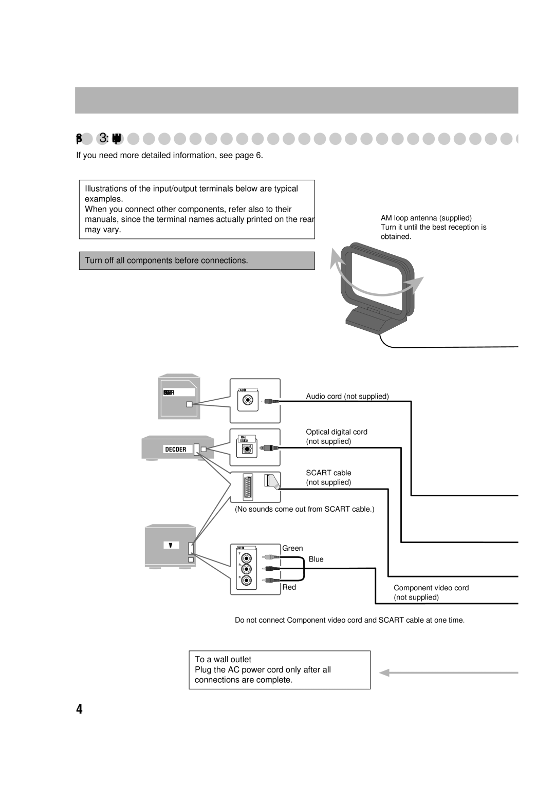
Moreover, the LVT1348-003A includes various input and output options, providing users with the flexibility to connect multiple devices. This capability allows for greater customization and creativity in audio and video setups, meeting the diverse needs of various users.
Overall, the JVC LVT1348-003A stands out with its robust build, extensive compatibility, advanced technology, and thoughtful design. As a reliable accessory, it not only enhances the performance of JVC audio and video equipment but also enriches the user experience, making it an ideal choice for anyone looking to elevate their audio-visual endeavors.