<Instructions for Assembly, cont’d>
|
|
|
|
| Caution | Avoid inserting fingers into the gap between the Frame and the Wall Mounting Unit when |
|
| putting these together, as fingers will get trapped, causing injury. |
| |
|
|
| |
|
|
|
|
|
|
|
|
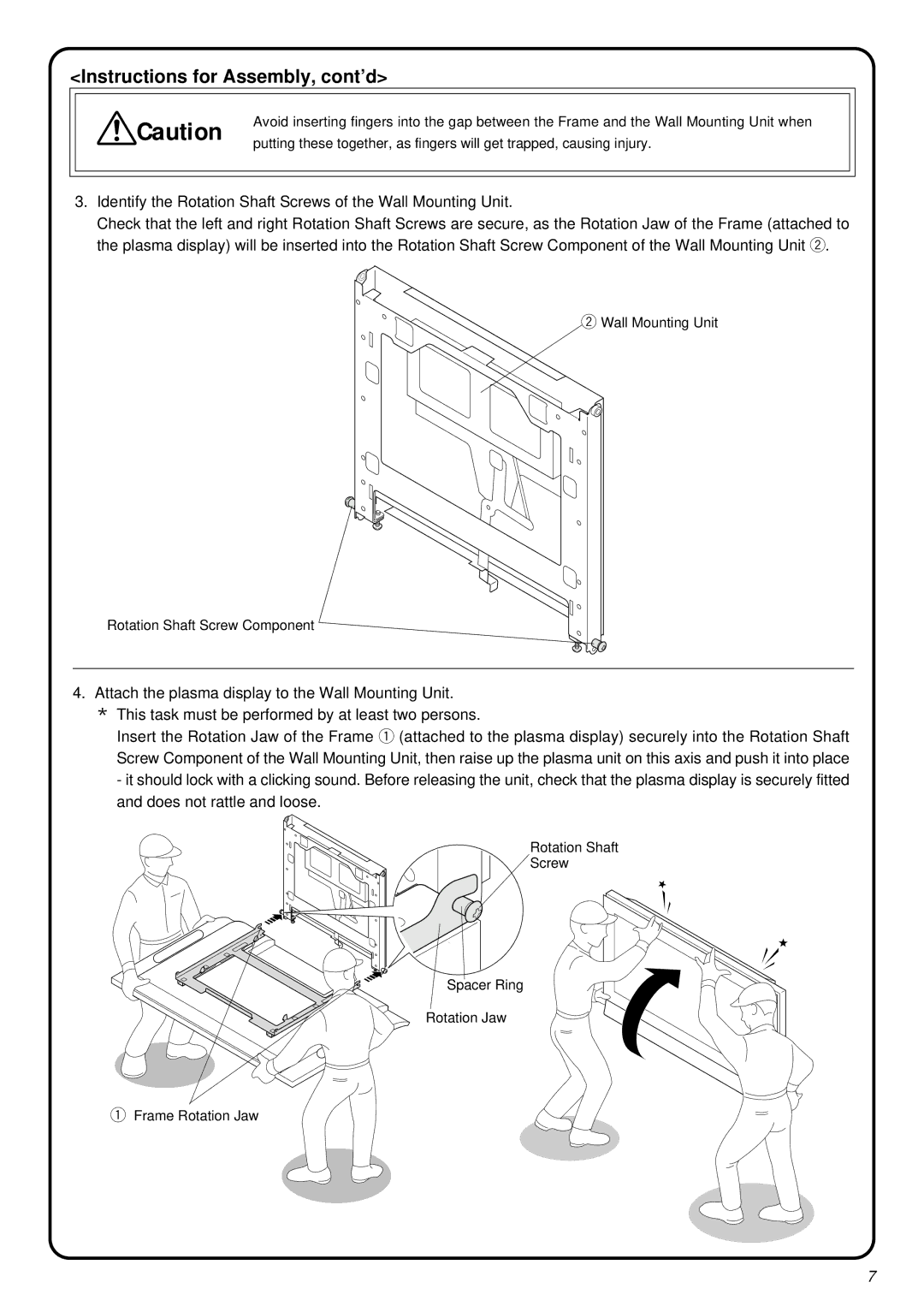
3.Identify the Rotation Shaft Screws of the Wall Mounting Unit.
Check that the left and right Rotation Shaft Screws are secure, as the Rotation Jaw of the Frame (attached to the plasma display) will be inserted into the Rotation Shaft Screw Component of the Wall Mounting Unit w.
w![]() Wall Mounting Unit
Wall Mounting Unit
Rotation Shaft Screw Component
4.Attach the plasma display to the Wall Mounting Unit.
*This task must be performed by at least two persons.
Insert the Rotation Jaw of the Frame q (attached to the plasma display) securely into the Rotation Shaft Screw Component of the Wall Mounting Unit, then raise up the plasma unit on this axis and push it into place - it should lock with a clicking sound. Before releasing the unit, check that the plasma display is securely fitted and does not rattle and loose.
Rotation Shaft
Screw
Spacer Ring
Rotation Jaw
qFrame Rotation Jaw
7
